Elevate your design and manufacturing processes with Autodesk Fusion
Congratulations to William Jones and his Union Pacific Big Boy model – winner of the Fusion 360 model of the month for March. Hear from Bill about himself, his inspiration for the model and details about his design process.
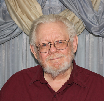
Hi everyone, my name is Bill Jones. I am 67 years old and I retired from the National Aeronautics and Space Administration (NASA) on January 1, 2016 after 41 years, 15 days of service at (what is now) the John H. Glenn Research Center at Lewis Field in Cleveland, Ohio. For nearly my entire career they identified me as an Aerospace Engineer. I hold BS, MS, and PhD degrees in Mechanical Engineering and Engineering Mechanics from Case Western Reserve University. That said, for nearly all that time I was really a computer person involved in making computers do things they had never done before.

My retirement project/hobby started by watching myfordboy making aluminum castings on YouTube. It occurred to me that I could make my own castings, which would allow me to build a (model) live steam locomotive in the manner of this video (beginning ~00:28). I settled on building a Union Pacific Big Boy model because the Union Pacific Historical Society sells CDs with PDF scans of the original drawings, all several thousand of them.
My plan was to develop CAD models of the various parts and then print those parts out on a 3D printer. From there, I would use those plastic (PLA) parts to make lost wax castings, and then machine those castings in my shop to produce my engine.
I picked Fusion 360 for my CAD tool mostly because my wife could tolerate the cost. Further, I was confident that a product from Autodesk would meet my needs.
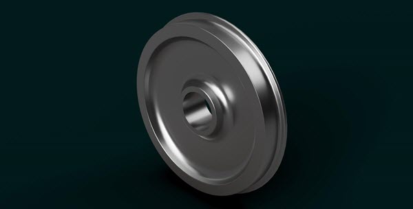
I started off a little over two years ago with basically no CAD experience. With some help from the Fusion 360 YouTube channel (and others) as well as some online instructional material, I started out with the simplest parts. While I don’t entirely recall, this wheel was among the first objects I translated into Fusion 360:

I design things in Fusion 360 “full size” to avoid confusion in translating dimensions. This wheel is a nominal 42” (106.68 cm) in diameter and would weigh a little over 1,100 lbs (527 kg). I then rely on the Fusion scale function to bring the part down to my model size. This has the further advantage that I can easily scale into any modeling category.
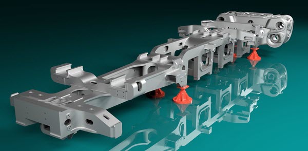
Once I began to feel comfortable with Fusion 360, I moved to the other end of the complexity spectrum – the locomotive beds – with the view that if I couldn’t generate the most complex parts, there would be little point in having all the rest of the parts library. Thus, I generated the beds for the front and back engines of the Big Boy. This is the bed for the back engine:

(More pictures can be seen in my Gallery projects. This is a link to a shared copy of the back-engine model.)
Sometime in the early twentieth century the railroad industry moved from built-up frames to one-piece, cast steel locomotive beds. These castings included integral cylinder blocks housing the cylinders, piston valves, and attendant steam passages. What is shown above represents one, single piece of cast steel weighing some 57,000 lbs (25,800 kg). I am boggled at the complexity of the sand molds that were necessary to produce one of these beds.
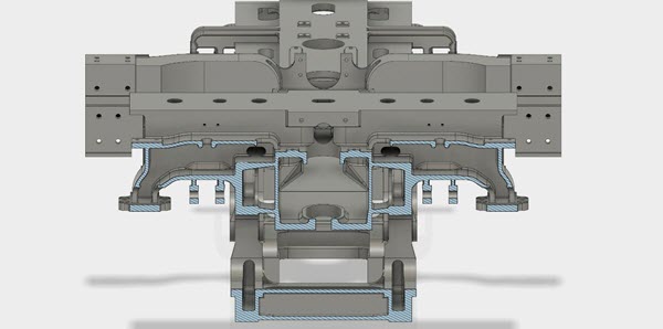
What is not shown in these pictures, and that I have barely suggested in my gallery projects, is the degree to which these locomotive beds are hollow. To the casual observer, the sides may look like simple 6-inch (15-cm) slabs of steel with cutouts for the axle boxes and spring rigging. In fact, those sides are hollow with an outer wall varying in thickness between 1.5 and 2.5 inches (3.8 to 6.3 cm), an inner wall generally about 1 inch (2.5 cm) thick, and a peripheral web between 1.5 and 3 inches (3.8 to 7.6 cm) wide joining the two, as shown in this cross-section:

This sort of sophisticated distribution of material holds true throughout the structure. And this was achieved before anyone had dreamed of finite element analysis.
I hope to cast and machine real parts from these CAD models. While the model needs to have most of the part details identified for machining, many must be left out of the casting model as being too fine to be reproduced in a casting.
Also, while these locomotive beds are mostly symmetrical, they do have some features that appear on only one side or the other. To meet this challenge, I have relied on Fusion 360’s Selection Sets feature. The model has a large selection set of bodies to be cut from the model prior to the mirror image/join operation that turns the left-side model into a whole locomotive bed.
After the symmetric bed is produced, another selection set joins asymmetric features, while still another removes asymmetric elements. To produce a casting model, these fine features are ignored and other selection sets join additional symmetric and asymmetric bodies to provide finishing material to be cut away in later machine work.
Overall, Fusion 360 has proven to be a key tool in the pursuit of my modeling project.