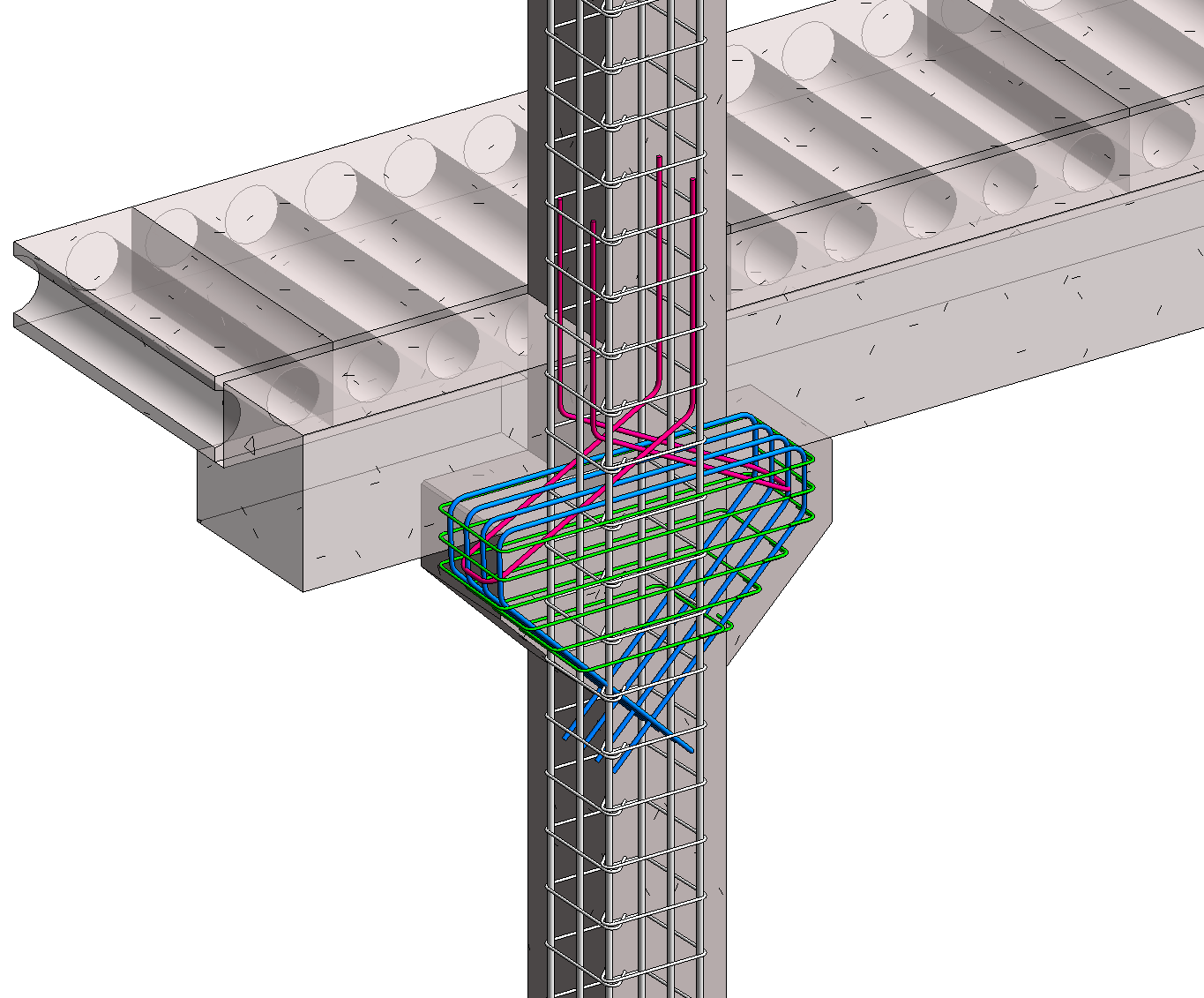
The use of linear precast elements generally means placing the connecting faces at the beam-column junctions. The beams can be seated on corbels at the columns, for ease of construction and to aid the shear transfer from the beam to the column. The beam-column joints accomplished in this way are hinged. Compared with a beam in bending, the corbel represents the special case of a very short cantilever.
To provide the right reinforcement designs for corbels we need to model rebars which are bent in more than one plane. In Revit you can model such rebar shapes very quickly and you have a great control over their geometry. In the next few steps I would like to show you how to do it:
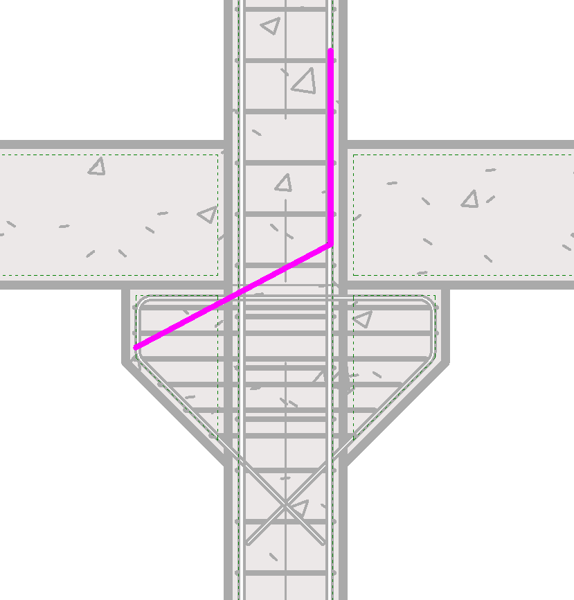
1. You simply begin sketching multi-planar rebar in the same way you do for a planar rebar.

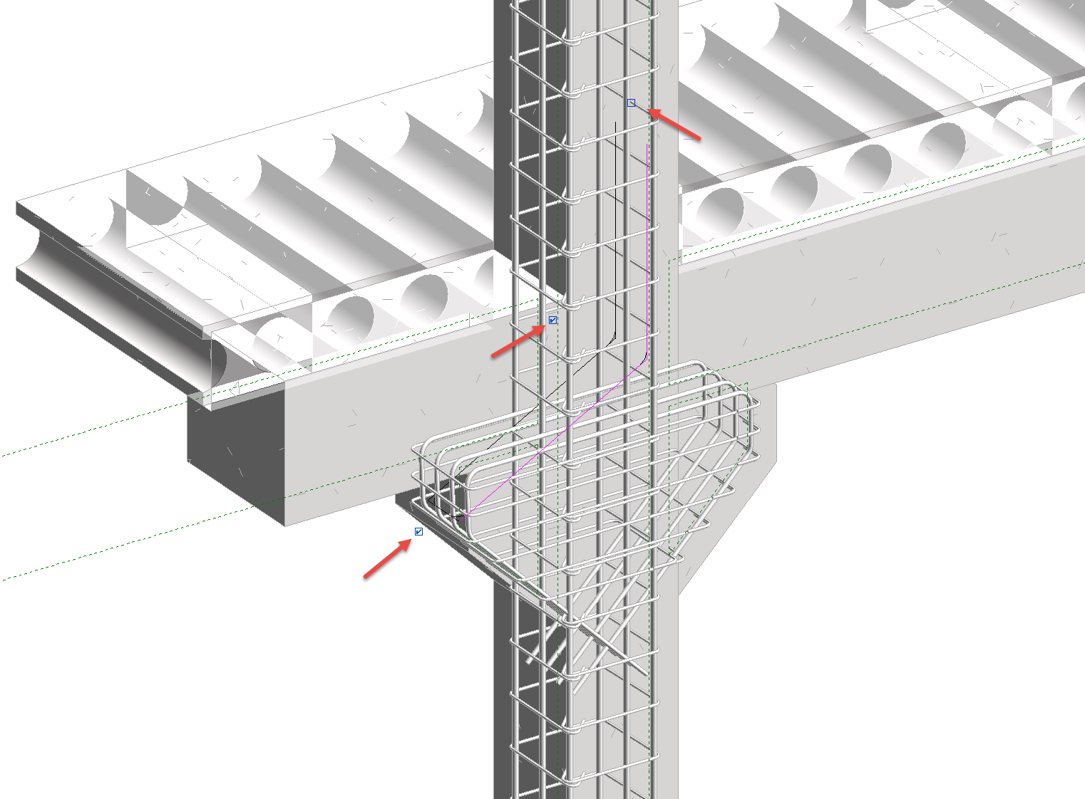
2. Next click Modify | Create Rebar Sketch tab Reinforcement panel -> ![]() (Multi-planar). The shape is duplicated and attached to the original by a connector segment of rebar.
(Multi-planar). The shape is duplicated and attached to the original by a connector segment of rebar.

This is best seen in a 3D view. Three check boxes are available to further edit the multi-planar rebar shape. Place your cursor over each box to see which tool they are.

3. Changes made to the source shape sketch will be mirrored to the duplicate copy and you may add hooks. Once sketching is complete, click Modify | Create Rebar Sketch tabMode panel ![]() (Finish Edit Mode) to accept the sketch and place the new shape.
(Finish Edit Mode) to accept the sketch and place the new shape.
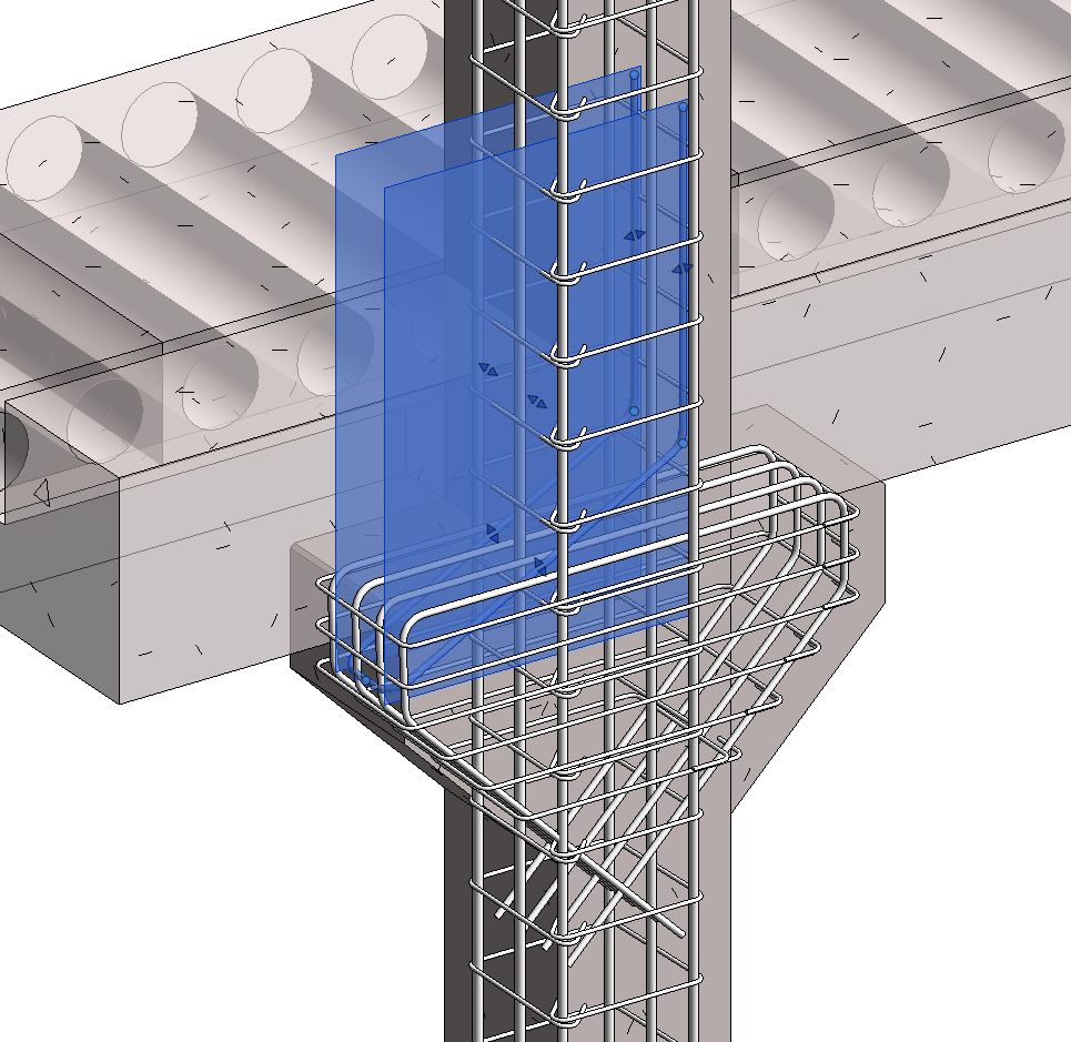
4. Use the rebar shape handles to make fine adjustments to the rebar location and shape.

You may need to adjust rebar visibility settings to see it properly. Check how to do it and read one of my previous posts: How to Deal with Rebar Detailing Visibility in Revit.

Learn more on rebar detailing in Revit:
Attention to detail – Revit for rebar detailing
Rebar Constraints Management in Revit
Reinforcement Connectors in Revit
Variable Rebar Distribution in Revit