& Construction

Integrated BIM tools, including Revit, AutoCAD, and Civil 3D
& Manufacturing

Professional CAD/CAM tools built on Inventor and AutoCAD
1 min read

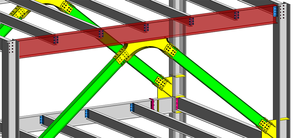
Revit 2018 includes a several major updates for steel design and detailing including over 130 new parametric steel connections. The Steel Connections for Revit 2018 add-in has heavily extended its connections categories and now has 24 tube connections, 23 bracing connections, 12 column-beam connections, and two new categories– Miscellaneous, Purlins & Cold rolled. With these additional connections the user can model different situations found in railings, purlin to rafter, purlin to column, bracing to beam or bracing to column.
These connections will help improve workflows between engineers and detailers by allowing them to exchange steel connection information to produce more accurate estimating and detailing, and reduce errors in fabrication.
Other new features
To improve the steel connections workflow users can now create steel connections between columns, beams and bracings using custom steel profiles.
Placing structural connections between steel framing members is dependent on a number of parameters of the elements in the connections. The Structural Section Geometry group of parameters in the Type Properties dialog lists these dependent parameters. In customized framing elements, the geometry parameters for connections may not exist and then they must be generated.
For such an element Revit analyzes the family and attempts to identify its section shape. The recognition methodology examines the family geometry and tries to match its section to common steel section shapes. Once it’s been matched, Revit generates the necessary structural section from the defined family geometry. This information is then used to create the connection according to the section sizes.
Furthermore, the information is used to run the code check for custom, parametric user-defined profiles.
The way the user can specify the primary element and the order of secondary elements within steel connections has been improved. When the user selects a connection, the generic connection symbol displays the primary element as a filled circle. The secondary elements are displayed as numbered circles. These numbers specify further order in the connection. The numbers can be easily picked and assigned to another element which updates the connection instantly.
This feature gives users greater control over modeling of steel connections in Revit.
Learn more on steel design in Revit:
By clicking subscribe, I agree to receive the AEC newsletter and acknowledge the Autodesk Privacy Statement.
Success!
May we collect and use your data?
Learn more about the Third Party Services we use and our Privacy Statement.May we collect and use your data to tailor your experience?
Explore the benefits of a customized experience by managing your privacy settings for this site or visit our Privacy Statement to learn more about your options.