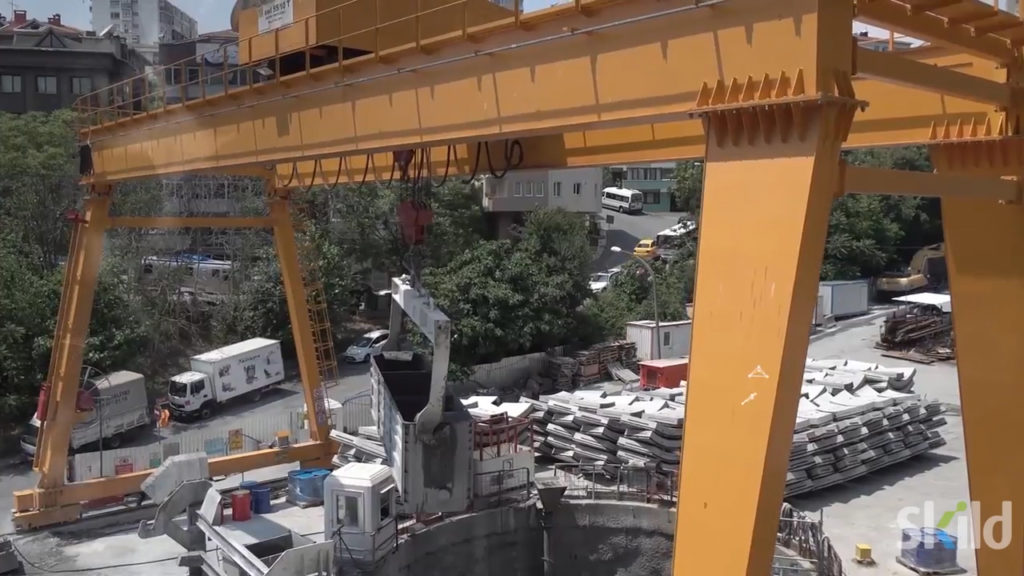
The Istanbul Kabatas-Mecidiyekoy-Mahmutbey Metro Civil and Electromechanical Design & Construction Works project, managed by Istanbul Metropolitan Municipality (IMM) – Directorate of European Side Rail Systems, is a mass transportation railway system and the first BIM for metro rail in Istanbul.
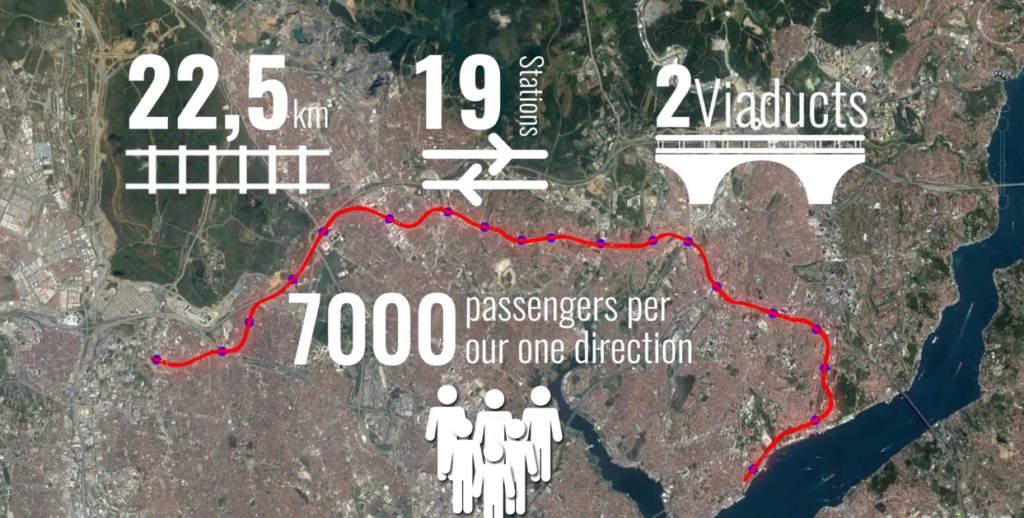
The metro line is located at one of the busiest and the most popular parts of Istanbul, a mega city with a population of 14.8 million. The main goal of the project is providing a high-quality and a safe transportation service to the passengers and to reduce the traffic problem by encouraging people to use public transportation. The line will be integrated with two tram lines, two metro lines and a funicular line and will be one of Istanbul’s busiest passenger lines. Furthermore, sustainability and energy efficiency are important with this public transportation system which aims to reduce carbon emission, to save costs and to follow an energy-efficient strategy for each phase of the project-design construction and handover/commissioning.
With help from Prota Engineering Design and Consultancy Services, Inc., and other subcontractors, the KMM Metro Line project is one of the first underground projects in Turkey designed on a BIM platform using 5D technology and the first BIM-mandated project in the public sector.
Objectives
- Integrate BIM methodology into a metro line project and to gain long term benefits throughout the lifecycle of the project in terms of time and budget.
- Implement BIM for the infrastructure design.
The investment in this project was considered as R&D costs, and inspires all transportation projects in Turkey. Approximately 635 km of metro line was tendered with BIM after observing contribution of BIM to the project.
Unique challenges
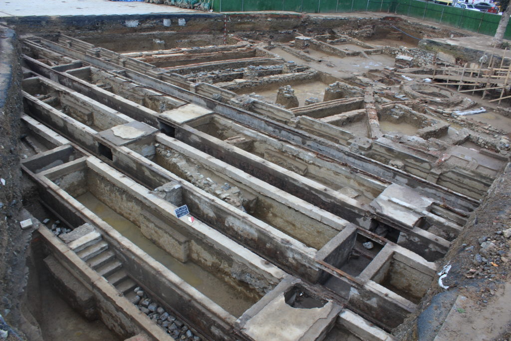
- There are various historical buildings throughout the entire route of the metro line which required a wide range of archaeological excavation works.
- Due to the crooked and intensive settlement in Istanbul, it is difficult to find convenient places for shafts and stations. Minimum expropriation and intervention in social life have been achieved with the benefits provided by creating 3D models.
- Different method statements had been used due to various construction conditions for each station; cut-cover, tunnel type, top-down methods due to low soil strength. This is particularly, due to the fact two stations are located on the sea side, serious ground problems occurred and high engineering solutions were used to solve these problems.
- Some coordination problems existed with design works and construction works among the three-contractor company. Most of the problems were the result of the adaptation process of BIM, because every project participant experienced BIM technology for the first time in a transportation project.
The BIM project use-cases included model authoring, existing condition modeling, 3D coordination, clash detection, cost estimation, project evaluation, 4D phase planning, room data sheets, virtual mock-ups and site utilization planning. The deliverables of the use-case are; architectural models, structural models, MEP models, terrain models, coordination models, RDS models, 4D simulations, record models and sheets. The BIM models are going to be available for use during operation and maintenance phase.
A new way of working – with benefits at each stage
Planning and preliminary design
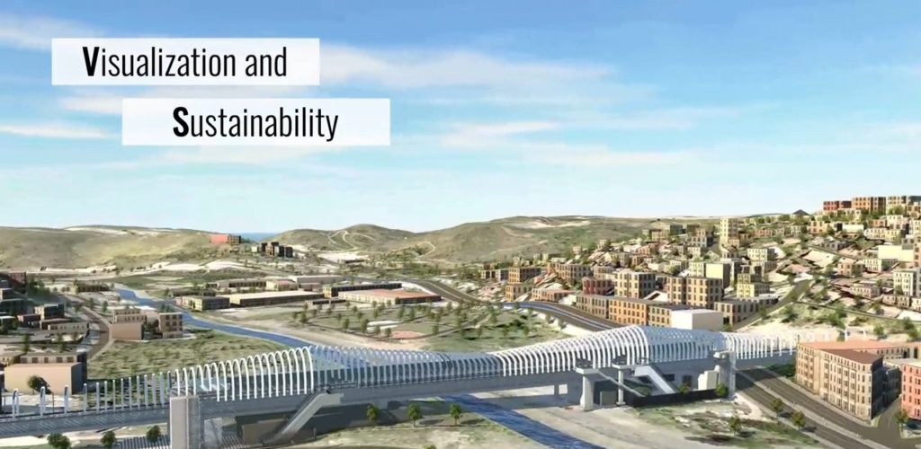
During planning and preliminary design stage, all design alternatives were generated as BIM models. The construction team discussed all constructibility issues based on these Revit models. Modeling and visualization activities accelerated the decision-making process for the contractor and the employer. At this stage, InfraWorks helped to visualize the stations and terrain conditions. And the model-based workflow allowed decisions to be made before the detailed design process.
The terrain was modeled by using AutoCAD Civil 3D. At model-based coordination meetings, the terrain conditions and the position of structures were evaluated via 3D models and some cut & cover platforms were transferred into tunnels based on these evaluations. Models of design alternatives also were used to explain the overall project situation to managers and to project coordinators of the employer. In addition, visualization helped inform the public–60K people were informed about the overall situation of the project.
In the planning stage, all alternatives were evaluated based on their costs which were obtained from MTO (material takeoff) and QTO (quantity takeoff) of BIM models. This situation helped to select the most feasible alternative during the planning stage.
Detailed design
During the detailed design process, different disciplines created BIM models.
- The tunnel models were created with Civil 3D, Revit and Dynamo. These models improved coordination among different disciplines.
- Dynamo was used for parametric modeling and data transfer for progress payments and follow-up. Especially because of the lack of a suspended ceiling in the project, MEP installation became a part of finish works.
- 3D models were used and detailed solutions were discussed in all project coordination meetings.
- Navisworks was used for 3D coordination and elimination of clashes. Material and equipment selection were also discussed in this stage. Prepared models and cost estimations were compared to make final decisions. BIM workflows helped selecting the most feasible and efficient alternatives.
Integrated analysis and simulation
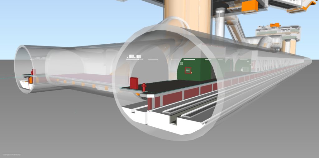
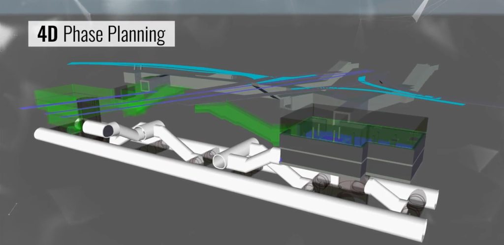
Through 4D simulations, tunnel excavation and final lining process work program verification was done in Navisworks. According to the simulation output, necessary scheduling revisions were done by the contractor’s planning team. With the 4D simulations performed at one of the integration stations, a construction work schedule was prepared that would not require the tram line to be closed. To increase the passenger safety and to protect the stations more efficiently, the fire protection design team performed CFD analysis in Autodesk CFD. Vibration analysis was performed for all stations and their surroundings to minimize the damage. Also, traction power and headway simulations were performed.
Communication and coordination
There are 200 stakeholders and 3850 people involved in this project including the employer, facility manager, consultant, general contractors, different design teams, subcontractors and suppliers. BIM technology, increased coordination and interoperability among stakeholders.
A common data environment was established and made accessible to every participant. Every stakeholder got access to the latest version of the project and models. Periodical coordination meetings were conducted through prepared models with all stakeholders in the project. Different disciplines of the project created their own BIM models. All the models were combined and coordinated on a BIM platform. Clashes were detected and eliminated in the combined model in Navisworks.
A trial version of Autodesk BIM 360 Glue was used for the first time. The contractor company plans to integrate BIM 360 for subcontractors and construction site teams. In design stage, all coordination meetings were conducted by considering construction and operation phases.
Construction
After completion of rough construction works, a robotic total station was used to scan the construction site by using 3D laser scan technology. Recap was used to view and prepare point clouds for Revit and Navisworks. 3D models were also created by using point cloud data. Existing conditions were compared with the design. Thus, the model was updated according to the site information and existing conditions of the project without the need of the as-built project phase.
The project team realizes 18% cost savings on their first ever BIM project including robotic total stations, 3D laser scanning technology and cloud access for all.
