& Construction

Integrated BIM tools, including Revit, AutoCAD, and Civil 3D
& Manufacturing

Professional CAD/CAM tools built on Inventor and AutoCAD
7 min read
When I first started using Revit, I had a hard time with the term Revit “families”. However, as I have learned more about Revit, I’ve realized Revit families are at the core of Revit and not only does the term itself have much more meaning to me but it helps me understand how Revit works.
Simply: the family contains the DNA of how to make an element in Revit, and when you author Revit families, you are writing the DNA code for an element. The family describes the basic geometry of the element, the behavior/relationships of the geometry, and defines the element’s parameters. When you place a family into a model, this DNA is used to make the element. If you need a different size of an element, the DNA in the family remains consistent and tells your element how to create a different-sized version.
In this article I will outline the basic workflow of making a Revit family and what to consider as you begin to create custom families.
Before creating Revit families, I personally like to organize my thoughts and plan what I am doing very simply on paper to give me an outline that helps me understand the geometry I will need. What is variable? What is not variable? What needs to stay in place? I can see how things might be related to one another and can start a list of parameters or information needed for the family.
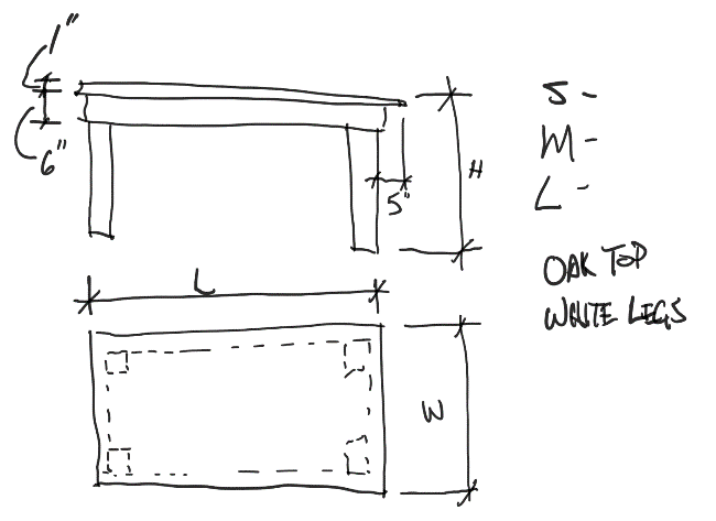
Example: Planning a Revit family for a table
The category – window, door, furniture, etc. — of a family defines basic behaviors. For example, a window must be hosted by a wall (it can’t exist by itself), while a column extends up from one level to the next. The category also determines how Revit treats the element for scheduling and controlling the visibility and graphics of the element.
In most cases there is only one template to use based on the category. Some categories, however, have multiple templates based on what will host the element i.e.wall, ceiling, or face.

Example: the Generic Model category offers multiple templates based on how the family will be usedWhen deciding which template makes the most sense for your family, consider how it will be used in a model. For my sample table family, I’ll use the Furniture family.
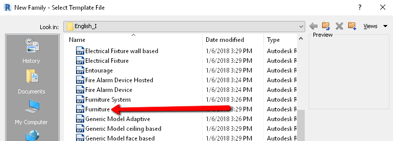
If you want a family that can change size or has moving parts, create a parametric family –that is, one that uses parameters to control its behavior. In this case, you need to build a framework using reference planes and reference lines.
For example, if you are building a table, create reference planes to define the front and back edgesand the right and left edges of the tabletop. Add more reference planes to define the position of the legs of the table as they relate to the table edges.
Use reference planes to define all critical positions, static and variable, in the family. The geometry that you create for them will be constrained to the reference planes so when they change position, the geometry will follow.
Using reference planes as a framework like this is more reliable than constraining just geometry. If you use geometry faces for constraints, you can sometimes encounter “Can’t make type” errors because a constraint becomes invalid. This issue is less likely when constraining to reference planes.
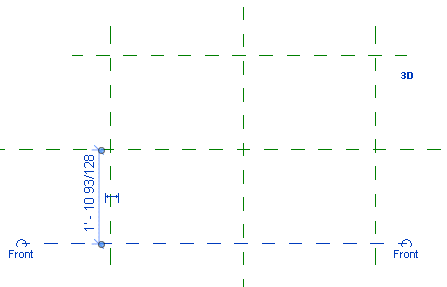
Example: Creating reference planes for a table family
Reference lines serve the same function as reference planes, but they can be used to constrain angles. If you need to define an angular condition, like the swing of a door, use a reference line. But in most other cases, a reference plane is preferred.
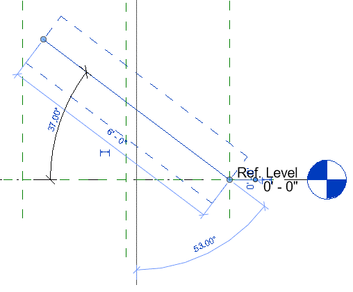
Use reference lines to constrain angles
After the framework is established, you can place constraints to control it. Apply constraints with dimensions and alignments. Dimensions are locked, set as equal, or labeled with a parameter so you can control the position of the reference planes in the framework.
When creating constraints, define both flexible and static conditions. In the table example, the tabletop edges (size, Length x Width) are flexible and labeled with a parameter. The position of the legs is static and always a defined distance from the table edges. Both conditions must be defined so that when the table changes size the legs will follow.
In the following example, Length (L) and Width (W) constraints have been added to the reference planes shown in green. Equality constraints have also been added so when Length and Width change, the center remains in the same position. The reference planes shown in red are constrained by the 5” dimensions. When Length and Width change, the red reference planes change with the green reference planes and maintain their distance 5″ away.
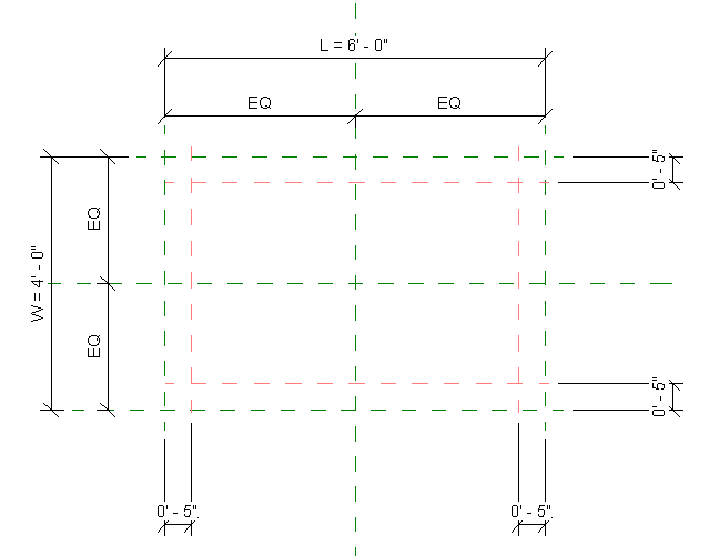
Example: Adding constraints to the table family
As a best practice, build the framework for one piece of geometry, apply the constraints, and then flex the family to be sure the constraints are working. Flexing the family means changing parameter values and verifying that the framework moves and repositions itself as expected. To help with flexing, add a few family types so you can quickly change the parameter values.
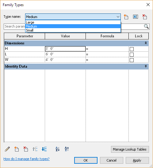
Example: Adding family types
It’s also OK to not apply any constraints if you are creating a family that is not intended to change, as parametric constraints are not a requirement for a family but offer a way to create more flexible content. When first making families, make them without any constraints to familiarize yourself with the tools in the Family Editor before you tackle a parametric family.
With the framework and the constraints in place, you can now add geometry. The faces of the geometry or the sketch lines are aligned and constrained to the framework. When you sketch directly on the reference planes of the framework, automatic sketch dimensions are added and constrained without any action. This is Revit trying to understand your intentions. To see the relationships being established, turn on automatic sketch dimensions in the Visibility/Graphic Overrides dialog.
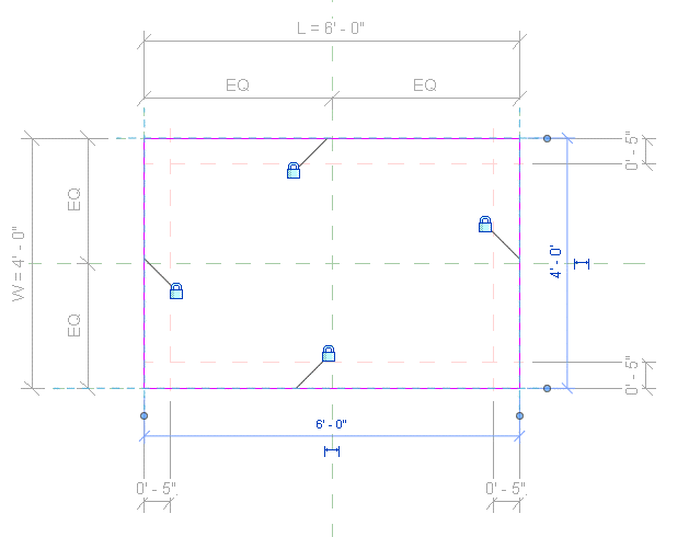
Be careful when constraining sketch lines of geometry. Constraints created in sketches won’t be visible when the sketch is completed. Typically, this has no effect on the behavior of the geometry, but if you need to make changes to the constraints or troubleshoot geometry that’s not working when flexed, constraints in sketches are more difficult to locate and troubleshoot. As an example, you could constrain the size of the table leg by creating a constraint in the sketch, or you could create an extra set of reference planes to control the size of the table leg more explicitly. Either option will work. The extra set of reference planes is easier to troubleshoot, but it takes more time to author.
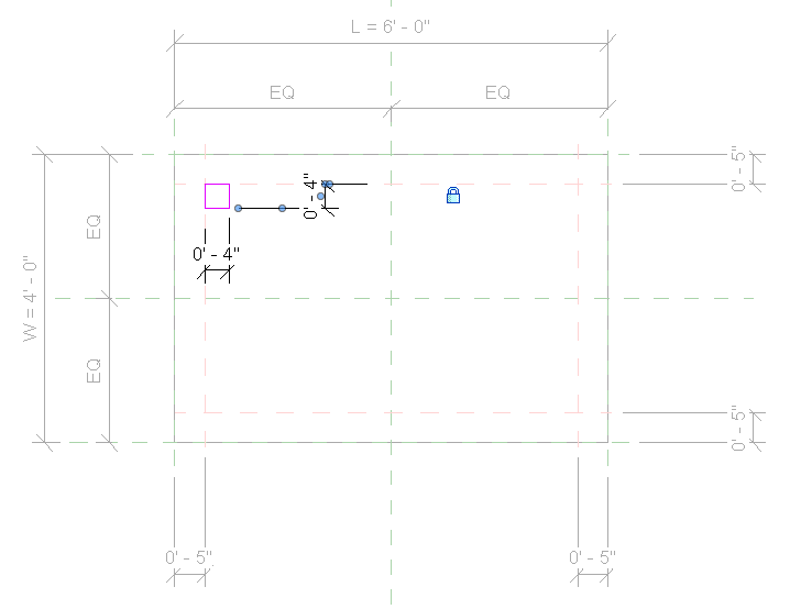
You then repeat the process of adding the framework, constraints, and geometry for each piece of geometry in the family. Be sure to flex and test to ensure the family is working as you expect. If you don’t flex often, you may end up with something not working quite right; then you must undo many steps and constraints to find the problem. Slow and steady progress may save you frustration, especially as you are first learning how to build families.
Materials – Each piece of geometry needs to have a material defined.. If the family will always be the same material, material can be defined explicitly in the family by selecting the geometry and setting a material property. If your family has potentially different finishes available, instead of explicitly defining the material, apply a parameter instead. Then the material can be set after the family is placed in a model.
Formulas – You can define parameter values explicitly, or they can be defined using a formula. Formulas are very powerful and let you define relationships between parameters in a family. For example, you might set the length and width of the table to be functions of each other to always maintain a certain proportion when either the length or the width is changed.

Visibility – Geometry in a family can be set to not be visible in some situations. As an example, a family for a light fixture is represented symbolically in a plan view but displays the model in a 3D view. The geometry is set to not be visible in the plan view but is visible in a 3D view.


Creating families in Revit is a rich topic, and there is no one way to explain “How do I make a family?” This article tries to explain the basic steps you should consider as you set out creating families. You are creating the DNA for the family, building the instructions and telling Revit how the family should behave. Take it one step at a time, building the framework, the constraints, and the geometry for each piece of the family. Test each part by flexing as you go. It may feel very time-consuming when you first start, but it’s rewarding when you get your first parametric family working just the way you want it.
Here’s to you, wishing all the best to you and your families!
By clicking subscribe, I agree to receive the AEC newsletter and acknowledge the Autodesk Privacy Statement.
Success!
May we collect and use your data?
Learn more about the Third Party Services we use and our Privacy Statement.May we collect and use your data to tailor your experience?
Explore the benefits of a customized experience by managing your privacy settings for this site or visit our Privacy Statement to learn more about your options.