In this post of the Structural Precast series, I will cover the Mounting Parts functionality.
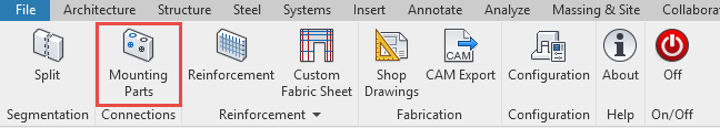
Structural Precast Extension for Revit has a tool (Mounting Parts) that automatically adds grout tubes, extra rebars, electrical sockets, cable ducts, or other model components to the corresponding precast assemblies. The precast walls and slabs will contain the logic that is required for fabrication, minimizing problems in the factory or on site. When the Mounting Part command has been used and rebars are added then the weight of the assembly is updated automatically too.
The workflow is straightforward. After all the extra components or rebars have been modelled, press the “Mounting Parts” command. These components are automatically added to the right assemblies, based on their location and the boundaries of the assemblies.
The precast assemblies will contain location information needed for the fabrication process, with respect to the shell and the face. Solid walls, solid slabs, and hollow core slabs are massive elements with one shell. Each shell has two faces: near face – NF – (visible face when element is placed on the production table) and far face – FF – (invisible face when element is placed on the production table). By using the Mounting Parts command, the location parameters are automatically added to all embeds.
Watch video:
For more posts on structural precast in Revit, check out these past articles on the Revit blog:
- Autodesk Structural Precast Extension for Revit 2019 Update 1: Delivering more automation
- Adding Grout Tubes to Precast Walls using Dynamo
- Segmentation of Precast Walls in Revit
- Structural Precast for Revit – Configuration Settings
- Autodesk Structural Precast Extension for Revit Software Overview
- Announcing Autodesk Structural Precast Extension for Revit 2018, a notable step toward the future of automatically making structural things
- Precast Column with Corbels in Revit