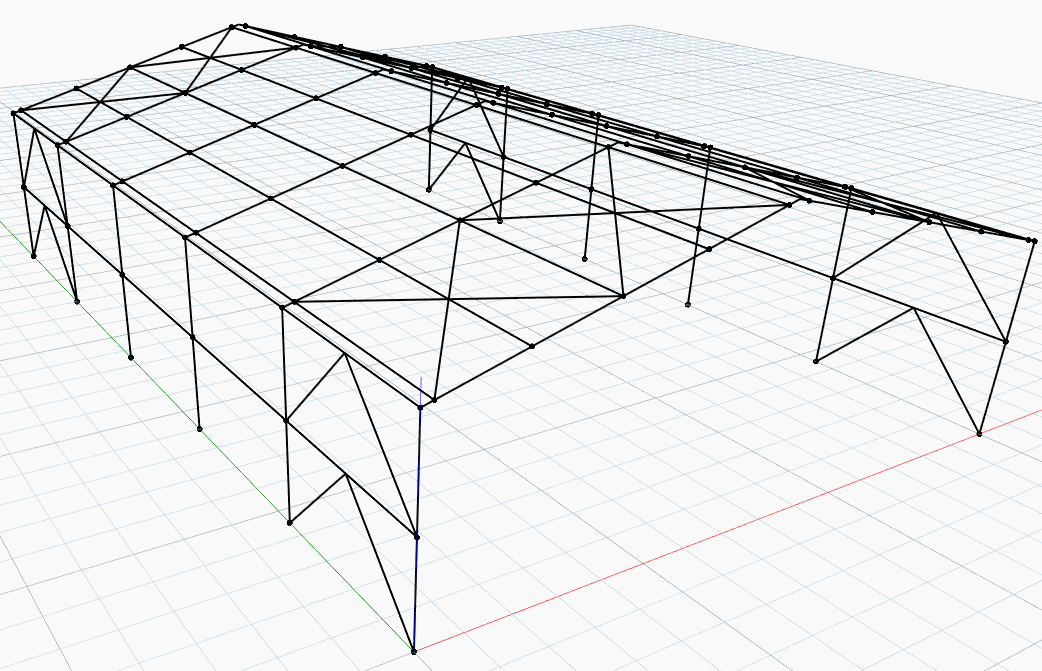
In this post I would like to show you how to create a fully parametrized portal frame geometry in the Dynamo environment.
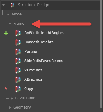
Recently, I added a few Dynamo nodes to the Structural Design package (version 1.1) to help you create such structural geometry.
Generally portal frames are used for single-story buildings, but they can also be used for low-rise buildings with several floors where they can be economical if the floors do not span across the building.
Let me walk you through details on these nodes and how to put together a sample script using them.
The first two nodes I would like to talk about create a 2D frame geometry (Fame.ByWidthHeights, Frame.ByWidthHeightAngles). They do the same thing and they differ by input parameters only.

insertionPoint – Insertion Point. Default value: (0, 0, 0)
vector – Vector in the 2D frame plane. Default value: (1, 0, 0)
width – Frame width
height1 – Column height
height2 – Roof height
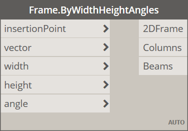
angle – Beam angle. The angle has to be greater than or equal 0 and less or equal than 60 degrees.
The Frame.Copy node helps you duplicate your 2D input frame geometry with a specified spacing between frames. The spacing can be equal of varying.
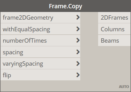
frame2DGeometry – 2D Frame geometry. Input value should have the following data structure: Curve[Column[], Beam[]]
withEqualSpacing – Spacing type. True = equal spacing, False = varying spacing.
numberOfTimes – Number of times a 2D frame should be copied when spacing between frames is equal.
spacing – Spacing value between frame when distance between them is equal.
varyingSpacing – Varying spacing. Default value: [6, 5, 4, 5, 6]
flip – Toggles the frame orientation.
The Frame.Purlins node creates purlins elements between rafters.
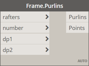
rafters – Rafters.
number – Number of purlins.
dp1 – Start offset.
dp2 – End offset.
The SideRailsEavesBeams node creates side rails and eaves beams between columns.

columns – Frame columns.
heights – Z coordinates of beam ends.
The last two nodes I would like to talk about create X and V bracings.
points – Element end points.
zones – Frame zones. A zone is a space between 2D frames, e.g. between frame #1 and frame #2 we have zone #1, between frame #2 and frame #3 we have zone #2 etc…
Building a sample script using the nodes I covered is easy. Simply connect these nodes in this way…
…to get the following output:
The final script covered in this post can be found in the extra folder of the Structural Design package.
For more posts on the Structural Design package, check out these past articles on the Revit blog:
Learn the Power of Dynamo for Automated Reinforcement Detailing – Part 1
Learn the Power of Dynamo for Automated Reinforcement Detailing – Part 2
Structural Design package version 1.0.5
With the Structural Analysis for Dynamo package, structural engineers can optimize and automate their workflows to improve their productivity. Learn more:
Portal Frame with Structural Analysis for Dynamo Package – Part 01


