In my previous post I showed you how to create a fully parametrized portal frame geometry in the Dynamo environment.
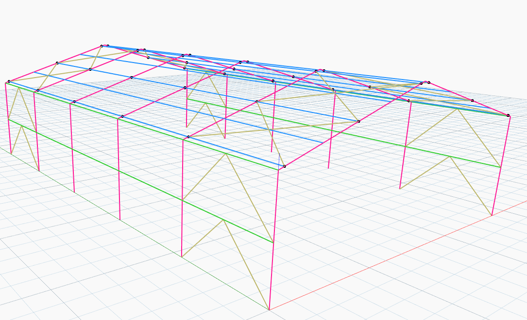
After the Dynamo geometry is set, you can create the analytical model representation of this geometry in the Robot Structural Analysis Professional environment.
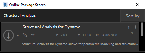
The Structural Analysis for Dynamo package enables parametric modeling and structural analysis workflows in Dynamo and Robot Structural Analysis Professional.
First, install the package. If you have never installed any package you may find this blog post useful.
Based on the Dynamo geometry, structural engineers can create an analytical model, and apply section shapes and boundary conditions such as supports and releases.
Engineers can also automatically apply structural loads which recalculate every time the structural geometry changes.
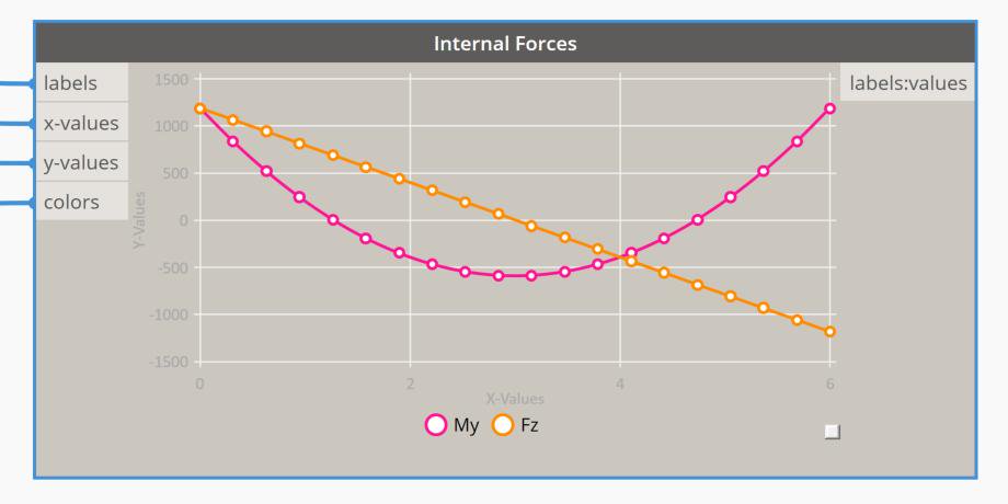
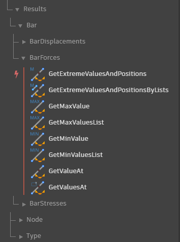
Structural engineers can review the results of this analysis in the Robot Structural Analysis environment or they can retrieve the results within the Dynamo environment.
With the Structural Analysis for Dynamo package, structural engineers can optimize their existing structural workflows or create new workflows that will improve their productivity.
Dynamo for Robot Structural Analysis helps users not only generate structural geometry but also:
Assign structural properties such as: section shapes, materials, releases etc…
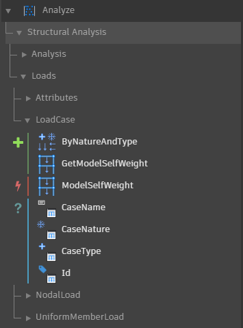
Create load cases and apply various types of loads:
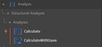
Run calculations:
And finally, display and retrieve results of structural analysis:
I would like to show you the process in the following example of a parametric portal frame.
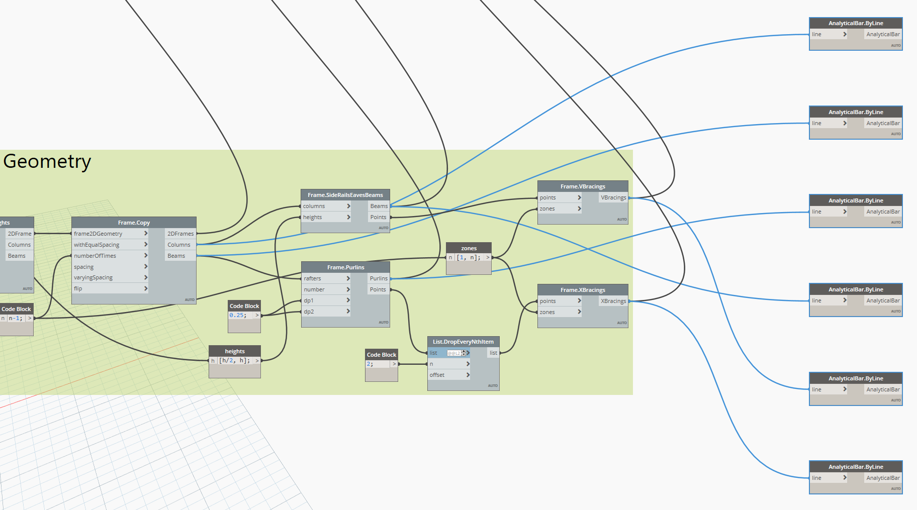
First, let’s create the analytical model representation of Dynamo geometry in the Robot Structural Analysis Professional environment.
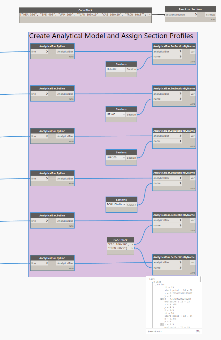
We need to connect the Dynamo geometry I covered in the previous post with the AnalyticalBar.ByLines nodes.
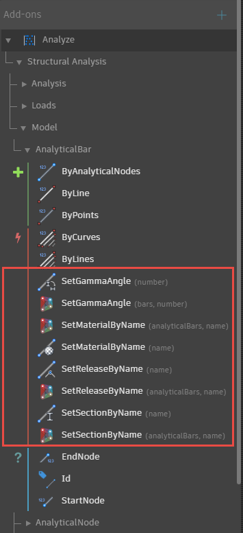
Before you assign cross-section properties to the analytical members, you need to make sure the sections are loaded in Robot. This can be done in the Robot project file you use, but this can also be performed in Dynamo with the Bars.LoadSections node for steel or timber sections.
If the sections are available in the active Robot project, then you can start assigning the right sections to the right analytical bars with the AnalyticalBar.SetSectionByName node.
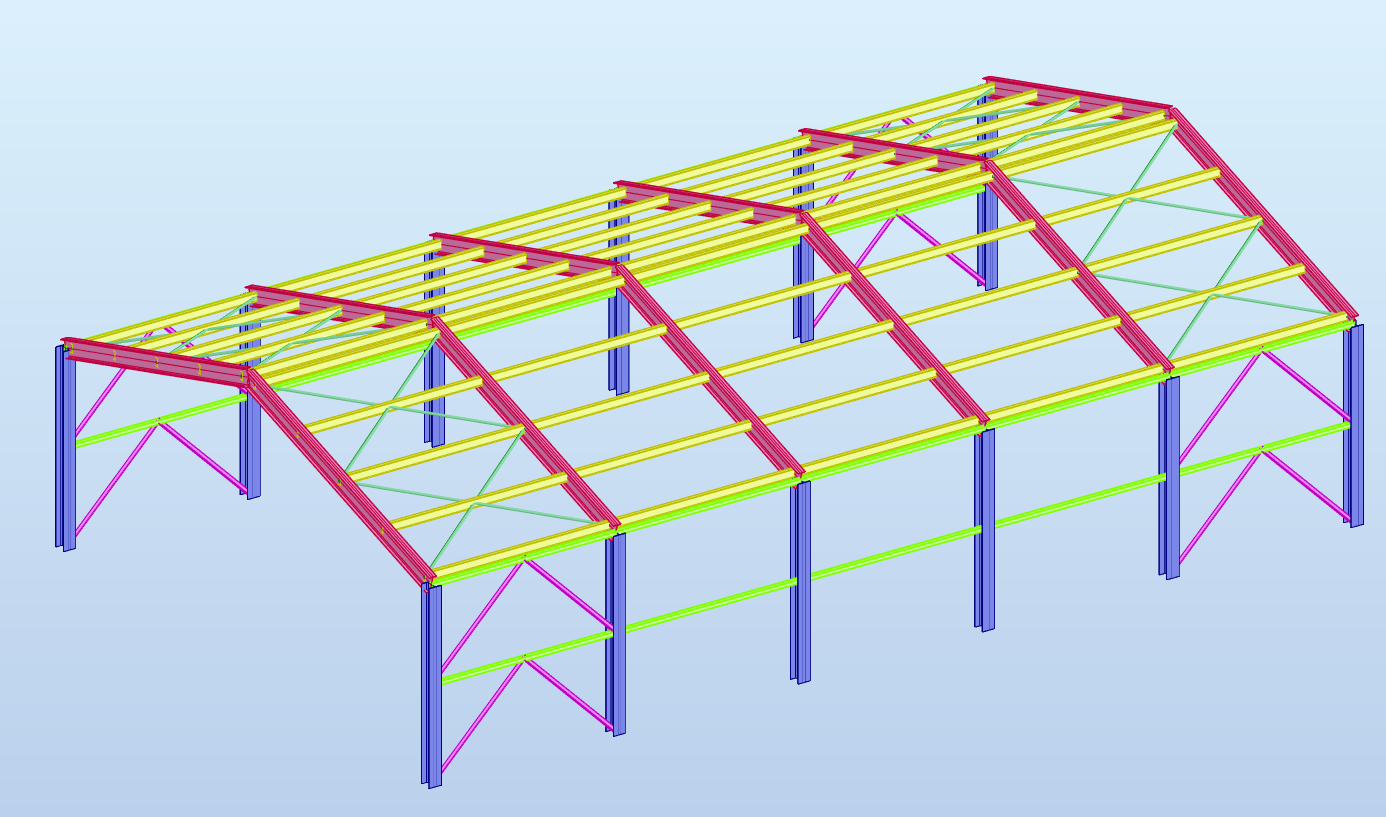
Let’s test it and click the Run button to see what we’ve got in the Robot environment.
In the next blog post I will continue this example and:
- assign a structural material to elements
- rotate purlins
- define boundary conditions
- create load cases, calculate load values and assign loads
- and finally run calculations and retrieve results in the Dynamo environment.