Authored by: Martin Schmid, Product Manager and Brandon White, Technical Marketing Manager
With the launch of Revit 2023, we shared a What’s New for MEP post, and mentioned the new electrical preliminary design capabilities in Revit. In this post, we will dig in with a little more detail to provide an overview of the capabilities.
This new functionality provides a way for electrical designers and engineers to start capturing electrical design requirements natively within Revit, in contrast to workflows reliant on maintaining data in spreadsheets, PDFs, and other disconnected repositories.
The workflow is designed to allow you to utilize linked DWGs, PDFs, or Revit models as the basis of load takeoffs within Revit. These load takeoffs, along with new capabilities to conceptually define electrical system elements, allow you to determine preliminary building load and load on main equipment components directly within the Revit environment. These takeoffs may then be used to produce documentation and schedules to communicate design concepts to stakeholders.

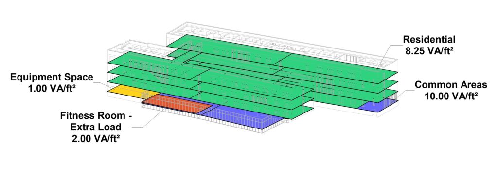
Figure 1: Area based loads represented in a 3D view to communicate design concepts to stakeholders.

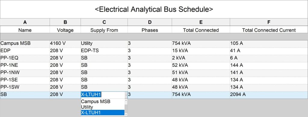
Figure 2: Schedules documenting loads, equipment currents, and power source requirements.
Core Concepts
There are two core concepts in this new workflow: 1) the creation of loads and 2) the creation of analytical system components. By creating the loads, the total load may be determined to estimate the service entrance requirements. Creating the analytical components, and associating loads with them, provides the ability to plan how loads will be served, and to determine preliminary ratings for the elements in the electrical system.
Loads
There are two types of loads in this new set of functionality: area based loads and equipment loads. Area based loads allow you to define the load classification, load density (e.g., power per area), and graphically define the region the load applies to, in order to determine the load contribution. Figure 3 depicts several user definable color-coded area based loads annotated with power density as defined by the designer or engineer.

Figure 3: Area based loads represented in a 2D view showing load types and power density.
Equipment loads allow you to capture other individual loads, such as main pieces of mechanical equipment, elevators, or other owner provided equipment that aren’t typically estimated based on an area power density basis.
Both types of loads may be connected to analytical busses to tabulate loads throughout the conceptual distribution system.
System Elements
The electrical system components consist of power sources (such as utility, generator, etc.), transformers, busses (which may represent panels, switchboards, busway, motor control centers, and the like), and transfer switches. By associating loads with the various system elements, and creating the system hierarchy by connecting them together, the loads may be used to determine preliminary ratings of the various distribution components.
Figure 4 below depicts the same area-based loads as Figure 3, however, this time the view is setup to convey the equipment each load is connected to. Additionally, the system browser depicts the entire system hierarchy, including generator, transfer switch, and elevator loads connected to the emergency and normal distribution. Finally, the schedule in figure 5 shows the total loads on each major distribution element.

Figure 4: Area loads depicting their power source.

Figure 5: Total loads on each distribution element.
These new capabilities provide electrical engineering load estimating workflows directly within the Revit environment, and extend the Revit workflow earlier in the process where design analysis and key decisions are made.
For more on preliminary load calculations in Revit, check out the video demonstrations below:
