& Construction

Integrated BIM tools, including Revit, AutoCAD, and Civil 3D
& Manufacturing

Professional CAD/CAM tools built on Inventor and AutoCAD
5 min read
Relevant MEP Fabrication products: CADmep, ESTmep, CAMduct, Revit
To have more consistency and predictable behavior in the generation of flat pattern developments, our team has prioritized several efforts to address a variety of user-reported issues. Historically, these issues would have been addressed in isolation, one by one, resulting in varying levels of inconsistency in the behaviors and flat pattern development results of various duct fittings. Taking a more holistic approach now, these efforts are more extensive in nature than one-by-one fixes. By doing a comprehensive evaluation of the logic, we hope to resolve a variety of issues, and at the same time, put into place much needed test automation to maintain the long-term health of the code and avoid unexpected changes in future behaviors, as we continue to address other types of issues that are dependent on this first effort. This effort for “Straight Adjusts” is the first step in starting to tackle the other improvements related to “MEP Fabrication Data Quality” that have varying levels of dependencies on how parts are expanded into flat geometry. Said another way, other improvements depended on addressing this area first.
The focus for the 2024 release was to resolve flat pattern development issues which were a result of inconsistencies in how the “Straight” property on connectors interacts with the “Extension” related properties at the end of rectangular fittings.
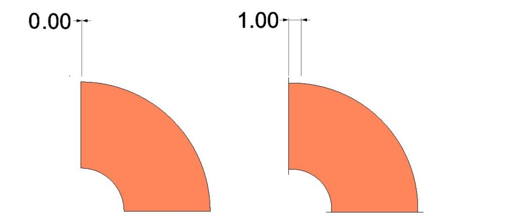
Generally, the Straight property on connectors applies a defined minimum straight length at the ends of fittings. For example, the image on the left shows an elbow (such as pattern 4) with 0 Top Extension and 0 Bottom Extension. The image on the right shows the effect of this behavior after applying a connector with a Straight value of 1.0. We’ve taken a comprehensive pass through all patterns to have better consistency and addressed several issues along the way.
An example of the prior inconsistency where the Straight setting from the connector would not affect the part is shown below. In this case, the applied connector has a Straight value of 2.0, and the part has a user specified dimension of 1.0. In the image on the left, the connector’s Straight 2.0 distance is not applied to the “f” dimension in prior releases. In the 2024 Release, the behavior has been improved to be more consistent.
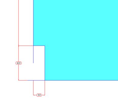
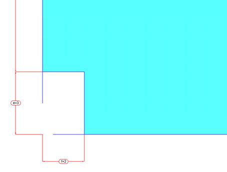
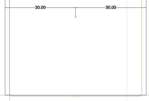
These inconsistencies in prior releases also had knock-on effects on other aspects of generating flat pattern developments. For example, holes for taps, holes for stiffening reinforcement, notches, splitter holes, and the like, may have been unexpectedly applied. In the example below, the image on the left shows the hole for midpoint stiffening reinforcement in the development previously adjusted unexpectedly due to the connector applied Straight. The image on the right shows the expected position of the stiffener in the 2024 Release.
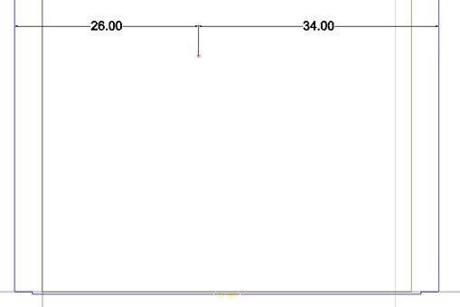
Finally, previously, the development preview did not clearly depict the finished fitting outline, and the computed area “Item Duct Area (No Allowances)” value was not consistently reporting the finished silhouette area of the fitting. In the images below, note the position of the arrows pointing to the grey line across the width of the elbow. This made it difficult to interpret where other aspects of the development, such as stiffener holes (shown in red), were relative to the finished fitting outline. The image on the right shows the improved finished fitting outline where the position of the stiffener hole relative to the fitting end is more easily validated. Also note that the corrected area value reflects the silhouette area of the finished fitting.
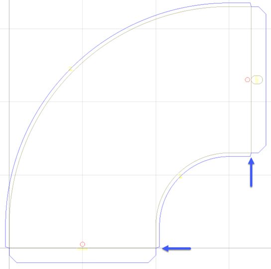
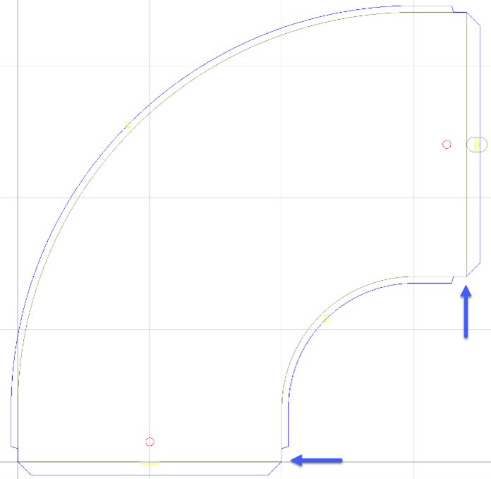
The above examples are illustrative of the types of behaviors that have been refined to provide better predictability and consistency across all parts that share similar characteristics. Due to the interdependency of a wide variety of settings, it is not feasible to attempt to enumerate all the applicable conditions and cases that have been improved to make the behavior more consistent.
The list below enumerates some key patterns that have functionality related to this connector Straight property adjustment behavior.
| Fitting Type | Pattern Numbers |
| Parallel Bend and Reducer | 1126 |
| Parallel Bend and Square to Round | 1127 |
| Parallel Bends | 1124, 1125 |
| Parallel Tapers | 1128 |
| Rectangular Bend | 3, 4, 17, 20, 22, 23, 250, 251, 354, 420, 421, 430, 431, 526, 761, 819, 943 |
| Rectangular Branch | 7, 417, 947 |
| Rectangular Branch on Rectangular Straight | 32, 150 |
| Rectangular Branch on Round | 904 |
| Rectangular Chimney | 343 |
| Rectangular Double Radius Offset | 836 |
| Rectangular End Cap | 12, 401, 958 |
| Rectangular Grille Box | 19, 21, 26, 31, 382, 861, 956, 957 |
| Rectangular Junction | 10, 14, 18, 800 |
| Rectangular Offset | 6, 11, 30, 252, 366, 460, 461, 955, 979 |
| Rectangular Radius Offset | 9, 330, 367, 939, 944 |
| Rectangular Taper | 2, 27, 253, 342, 440, 441, 920, 942, 959, 1148, 1178 |
| Rectangular Tee | 5, 13, 255, 470, 471, 945, 954 |
| Rectangular to Oval | 104, 134, 137 |
| Rectangular to Round | 8, 28, 29, 34, 254, 324, 338, 450, 451 |
| Rectangular Trousers | 328, 480 |
| Reducing Bend | 953 |
| Square Bend | 952 |
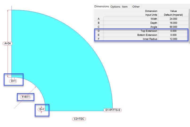
One final note regarding maintained behavior: When the connector is enforcing minimum length, there are overrides to prevent fitting ends from overlapping or shifting the model in potentially undesirable ways. As a result, the dimensions a user inputs for a part, including the Top/Bottom Extension, and the Inner Radius as exemplified in the image below, may not reflect the result when measuring the model. For example, values shown in the property grid, printed worksheets, and labels may not match the actual resulting geometry when measured in the model on a flat pattern development. For example, a rectangular connector may have a Straight parameter value of 1.0,” however, a user may set the Top and/or Bottom Extension to some value less than this. The image below shows a user input length of 0.0”. In such a case, the 1.0” from the connector is enforced, resulting in the “D” and “E” dimensions on the model and related geometry in the flat pattern development reflecting that value. Further, the Inner Radius, explicitly set as 12.0”, is overridden to 11.0”, again, to preserve the fitting endpoints. This is an area of legacy behavior that we’d like to improve at some point to provide more clarity regarding these ‘entered’ vs. ‘overridden’ values, but it presently isn’t something that is a priority for a planned project.
This work provided the opportunity to improve the foundation for future improvements. Additional areas under consideration related to “MEP Fabrication Data Quality” may be found on the Revit – MEP public roadmap
By clicking subscribe, I agree to receive the AEC newsletter and acknowledge the Autodesk Privacy Statement.
Success!
May we collect and use your data?
Learn more about the Third Party Services we use and our Privacy Statement.May we collect and use your data to tailor your experience?
Explore the benefits of a customized experience by managing your privacy settings for this site or visit our Privacy Statement to learn more about your options.