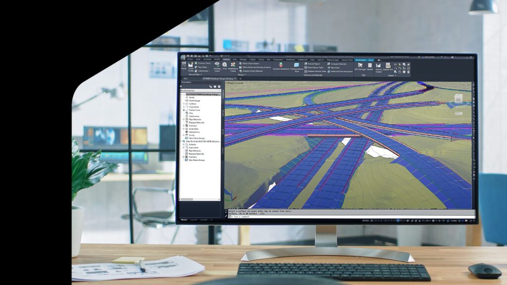
Great road design is about engineering a safe, efficient way to get around — and it relies on accurate modeling of real-world conditions, from traffic flow to topography.
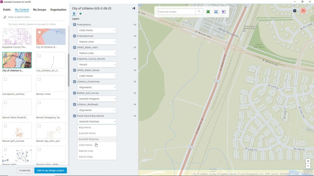
Autodesk Civil 3D is a powerful application for roadway design that allows seamless integration with geographical and environmental data via the Autodesk Connector for ArcGIS.
Designers can quickly create detailed terrain models in an online collaborative environment accessible by project managers, engineers, contractors and owner-organizations, streamlining workflows in critical and complex infrastructure projects.
Learn how with Part 1 how to design roadways in Civil 3D: gathering GIS data and creating surfaces.
Improve data exchange with the Autodesk Connector for ArcGIS
Road projects require vital information such as traffic data, contour data, flood plain maps, parcel maps, and Right of Way data, typically available from site owners and public agencies.
Gather the data you need in one place, by creating a new ArcGIS map, then add each dataset from online sources or local hard drives.
See it in action: In a roadway design project for Douglas County, Colorado, the ArcGIS map linked to the county’s databases that contained information about historic zones and protected lands, as well as road centerlines and topographic data. Designers can import this information into project design files to develop roadway solutions that take these factors into account.

Enhance your design by adding GIS layers to your Civil 3D projects
It’s easy to establish the base design in Civil 3D by starting a new drawing and defining the project coordinate system. Use the Autodesk Connector for ArcGIS to open the view space and specify your area of interest.
From My Groups, you can select layers of information to import from the ArcGIS library you just created. For example, importing roadway centerlines as alignments adds these over the base drawing, where you can view the linework and check its geometry. (Roadways can be added as alignments or feature lines, according to what is defined in the ArcGIS library.) Under the Public tab, you can also search by keywords for available data about the area of interest, such as detailed traffic information to help understand the needed road capacity and how best to design intersections.
Create surfaces for detailed design development
To create another surface that models the existing ground, use the Map Import feature to pull in contour data from the ArcGIS library.
Check the elevations of the linework in the Properties tab to ensure accuracy. In the Douglas County example, this was verified against data downloaded at the county’s website.
In Surface Properties > Definitions, you have several options to finetune the new surface, including setting the weeding and supplementing parameters to help optimize modelling accuracy (and data load) against computing performance.
To validate the accuracy of the generated surface, compare the contour data with map lines by adjusting contour display intervals in Surface Style or turning off the imported data lines.
Save and share: Once this surface has been inspected and saved, create a data shortcut in your cloud-based ACC (formerly BIM 360) Design folder for easy access by other project members.
You can also create surfaces using point cloud, LIDAR or survey data in a similar workflow.
Improve accuracy of your designs with updated surface layers
Civil 3D has robust functionality to account for distinct changes in terrain, such as the edge of a pavement. To update your surface model with such topographical details, create a new surface by importing feature lines or 3D polylines that contain information about the varying elevations.
After adding your feature line layer from the ArcGIS library, go to Surface Properties > Definitions > Breakline. Draw a selection box around the objects of the feature line you want to include in the breakline surface.
Surfaces are formed by triangulation between data points, including the breaklines, but it may not always be precise. Correct inaccuracies by heading to Surface Properties > Surface Style and selecting Contours and Triangles. Use Edit surface > Delete line to remove unwanted breaklines from the triangulation by drawing selection boxes over them.
Combine surfaces to integrate terrain features
Finally, create a new surface file to bring together the surfaces you’ve built.
Select Definition > Edits > Paste Surface, then import the existing ground surface, followed by the breaklines surface and any other surfaces you may have.
If you need to analyze specific features or eclipse certain aspects in a review, you can create a hide boundary to only display what you want (without deleting the hidden parts). Open Surface Properties for the surface you want to modify and go to the Definition > Boundaries dropdown menu to add a hide boundary, or select a surface directly from the command line to act as the hide boundary.
If you need to remove a surface, head to the Edits option and select the surface for deletion. There are also many other ways to modify the definitions of a surface, depending on the data available in your ArcGIS library.By enabling the seamless digital integration of design and geospatial data, the Autodesk Connector for ArcGIS helps you create surfaces more accurately and quickly, facilitating collaboration and decision-making in the complex, multidisciplinary work of roadway design.
Watch the video: How BIM & GIS Integration sets you up for the demand of the future.
Stay tuned for Part 2 in our series of tools to try for roadway design.
