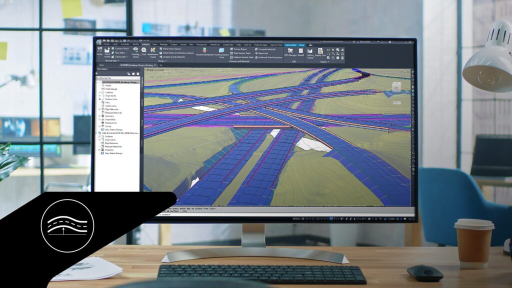
With the growing demand for smart road infrastructure, roadway designers need precise and flexible tools.
One critical aspect of road design is the roadway profile, which provides a detailed view of vertical changes in a road, helping designers manage gradients, optimize drainage, and ensure smooth and safe travel for all vehicles.
Autodesk Civil 3D provides comprehensive tools for working with roadway profiles. In this third installment of our learning series on designing roadways in Civil 3D, we’ll explore how to effectively create and edit roadway profiles.
Dynamic profiles for versatility and precision
A common method for creating roadway profiles in Civil 3D is by laying out Points of Vertical Intersection (PVIs) where two different gradients intersect.
Using a pre-established roadway alignment, designers select the surface for the ground profile, adjusting parameters here or using default settings. They then begin the design profile with the Profile Creation tool.
For layout by PVI, designers choose a vertical intersection, then add the curvature, defining it by length, radius or K-value. Civil 3D’s editing tools allow for easy revision later, if needed.
To add another PVI, designers can select a point in the profile window, then add a vertical curve associated with the PVI. The Free Curve–Best Fit command helps match the curve to the existing ground, based on precise coordinates, existing curves and lines, or by selecting points in the window.
Changes to the roadway’s horizontal alignment update automatically in the profile line and profile window, saving time and enhancing design control.
Detailed control of profile layout parameters
In the Profile Layout Parameters menu, designers can edit curve parameters: station, elevation, k-value, length of curve, and more. Changes are instantly updated in the profile window.
They can also edit curve parameters graphically, using the grips associated with each curve. Fixed points on the roadway profile can be maintained while adjusting other parameters.
For example, designers might need to maintain the gradient but move the curve location, or change the gradient while maintaining the end elevation or station. When they make the changes, curve labels automatically update, ensuring real-time accuracy.
In the Profile Layout Tools menu, the “Delete Entity” command removes a curve, reverting geometry to consist solely of the PVI, while “Delete PVI” removes a PVI between two curves, deleting both curve and point.
Boost accuracy with critical intersecting alignments
Intersecting alignments can be displayed in the profile view using the Add Crossing to Profile View option, helping coordinate different engineering considerations.
Designers can label each profile in an alignment, and dynamic label updates can help manage these critical points of intersection.
They can match adjacent alignments by superimposing their profiles. With the first profile selected, designers can choose Create Superimposed Profile to create a second version in the desired window. If necessary, the second profile can also be traced by laying out points and adjusting it using grips and other editing tools.
This function creates another profile for a given alignment, which can then be used in the corridor design integrating all roadway elements.
Learn more
With cities moving towards smarter roads, powerful and flexible roadway design tools are essential.
See how these forward-thinking road infrastructure companies are adapting road design using GIS, BIM and generative design technologies.
Stay tuned for the next part of our series, which will delve into roadway assemblies and the sub-assembly composer in Civil 3D.
Catch up on our previous installments here:
- Learn How to Design Roadways in Civil 3D, Part 1: Gathering GIS Data and Creating Surfaces.
- Roadway Design in Civil 3D – Learning Series Part 2: Roadway Alignments
- Learn more about Road and Highway Design using Civil 3D as part of the AEC Collection
