3D modeling has been around in AutoCAD for a long time now. Yet, so many users still are using just regular 2D AutoCAD tools to represent real 3D “things.” In this first of a two-part series, I would like to go over some tips and tricks for AutoCAD 3D modeling that may make it easier to jump into the world of 3D.
Wireframe Modeling
Wireframe modeling consists of using regular AutoCAD objects along with some 3D basic objects to generate your design. Here is a final layout of a house all done with wireframe modeling and some basic 3D tools. (Looks like a real 3D model, doesn’t it!)
Let’s go over some tips and processes that will aid you in the wireframe modeling process.
Command Tips for Wireframe Modeling
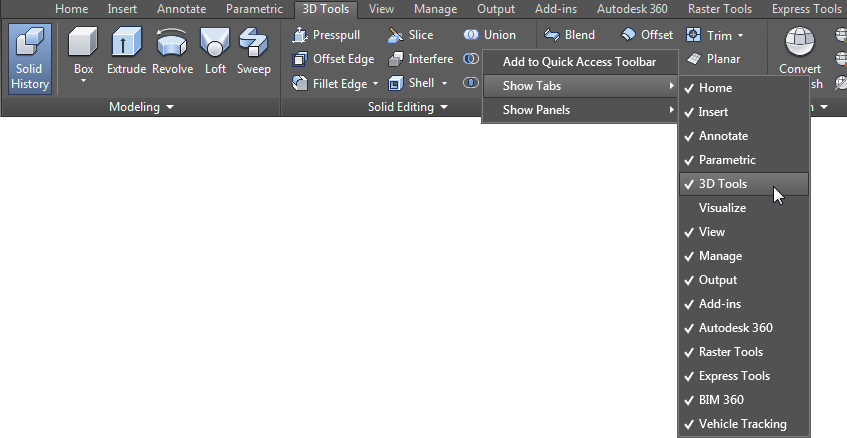
There are 3D tools in the Drafting and Annotation workspace. To add the 3D tools tab, right-click anywhere on the ribbon and add the tab.
For the complete set of 3D tools, use the 3D Modeling workspaces. Copy the 3D Modeling workspace, so that you always have the default workspace as a backup.
To ensure your workspace is always saved as you make changes, make sure “Automatically save workspace changes” is toggled on.
Viewing Tips for Wireframe Modeling
Use SHIFT+MIDDLE CLICK to rotate the view. And use the Viewport, Visual Style, and View Controls to aid you in the modeling process. These are located in the upper-left part of the active viewport.
In AutoCAD 2015, AutoCAD included the ability to size any of the viewports by hovering and clicking on the two vertical bars. You can add viewports by clicking the plus sign. Double-click the “+” for any viewport to maximize it.
UCS Tips for Wireframe Modeling
The UCS icon can be selected and used to rotate to a specific plane. To access additional UCS tools quickly, select the UCS icon and right-click on it. Each viewport can have its own UCS defined. Be sure to ALWAYS KNOW WHERE YOUR UCS IS!
To easily identify where the UCS is, set the UCS icon to display at the origin. To do so, select it, right-click on it, and choose UCS Icon Settings > Show UCS Icon at Origin.
To quickly rotate the UCS to a standard orthographic view (e.g., top, left, front, right, etc.), use the View Controls.
OTRACKing Tips for Wireframe Modeling
Use OTRACKing to aid you in getting to ANY geometric point. OTRACKing works in conjunction with your running OSNAPs. Remember, ACQUIRE, DON’T CLICK to get the point you want.
Trimming Tips for Wireframe Modeling
When you need to trim objects in the 3D world, make sure you check the Project command line options.
Converting 2D Objects to “Look” Like 3D for Wireframe Modeling
Regular AutoCAD objects can look like 3D objects. Lines, arcs, polylines, etc. can have a thickness applied to them, and they will look just like a 3D object. You add thickness to an object by selecting the object and changing it in the Properties palette.
To apply hatching to look like it is on a 3D plane, rotate the UCS to the plane of the 2D objects and run the command on that object.
“Hidden” Commands for Wireframe Modeling
To add shaded areas, you can use the following commands, depending on your needs:
- REGION
- SOLID
- 3DFACE
Plotting Tips for Wireframe Modeling
Use layouts and multiple viewports to display your design, and add dimensions and text in paperspace to avoid the concern for scaling.
OR there’s an alternative. Add them to modelspace, use annotation scaling, and rotate the UCS to the projection you want to annotate (i.e., Top, Front, etc.) Put dimensions on different layers so that you can viewport freeze them.
And there you have it—some AutoCAD 3D modeling tips and tricks for wireframe modeling. In the second part, we will cover some solid modeling tips and tricks.


