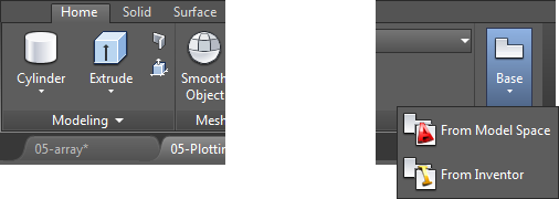
In the second installment of the AutoCAD 3D modeling tips and tricks series, we began discussing solid modeling. For this final article, let’s go a bit deeper with more on surface modeling, editing solid models, arrays, and plotting solid models!
Surface Modeling Techniques
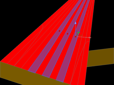
Almost all the solid modeling commands can also be used to create surfaces. The following commands allow you to create surfaces very quickly from standard 2D objects:
- RULESURF and TABSURF – Add a surface between objects
- REVSURF – Creating circular surfaces
- EDGESURF – Using edges to define a surface plane
To control the number of tabulations to be generated by the above commands, set the SURFTAB1 and SURFTAB2 variables appropriately. And to make it easier to edit surfaces created by the above commands, convert the mesh to a surface and then convert the surface to a Mesh surface.
To make mesh surface edits to multiple faces at once, you can select multiple surfaces first with certain commands by holding the CTRL key down, selecting the faces, and then running the command.
Using Arrays in a 3D World
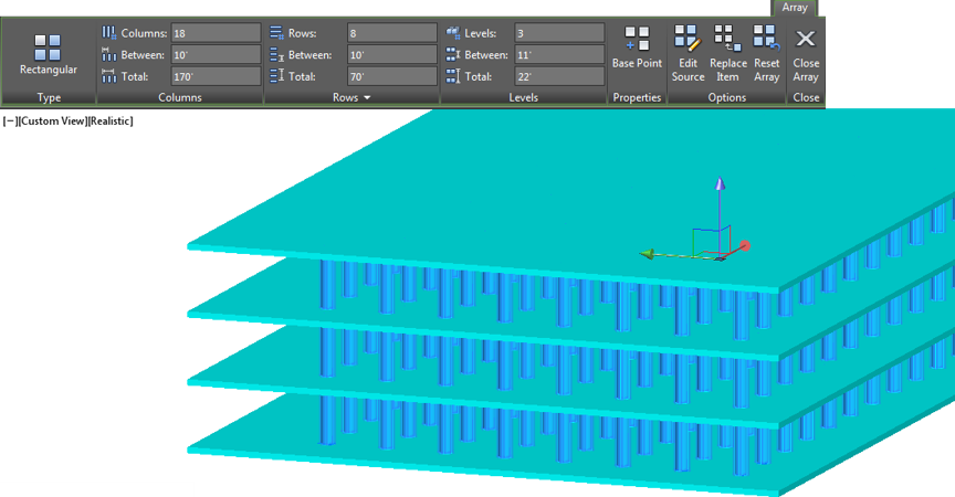
Arrays work with 2D or 3D objects. You can use the Levels option to add objects at an elevation.
Solid Modeling Editing Tips
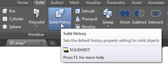
To make sure that a history is recorded for all solids in the drawing and edits can be made, make sure that the SOLIDHIST variable is turned on.
Select objects first and use the grips to make edits to different parts of a solid model or surface. To modify multiple locations when grip editing, hold the SHIFT key and pick additional grips. The grips will become “hot” grips.
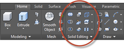
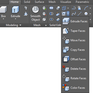
In the Home tab > Solid Editing panel > Edit Faces drop-down, there are many tools available to make edits to surfaces when grip editing or the Properties palette are not sufficient.
Plotting Solid Models Tips
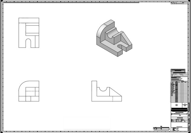
There are many ways to plot 3D models. The best way is to use the model documentation process introduced in AutoCAD 2012. Here are some tips and processes that will aid you in plotting models.
The model documentation process is started with a base view. The tool is located in the Home tab > View panel (or type VIEWBASE in the command line).
Double-click a drawing view to edit it. To easily edit drawing view, select it first and look to the contextual ribbon.

To access additional functionality with a section or detail view, simply hover over any of the grips to access the multi-functional grip menu.

And there you have it for tips and tricks regarding 3D solid modeling. Be sure to check out Part One and Part Two of the series as well. Happy 3D modeling!
