Have you ever had to resort to using a PDF scan as the background for a design? Here, I’ll take you step-by-step through the process to clean up a scan for a design. (And be sure to check out my other articles “No Contest: New AutoCAD 2017 PDF Import Conversion Explained” and “When PDF Import Isn’t an Option… AutoCAD Raster Design!” for even more helpful background information on PDFs and AutoCAD Raster Design as we tackle this next problem!)
For this article, I have a file that I’ve already determined can’t be converted to a DWG. So let’s take a look at how we can use AutoCAD Raster Design to clean up a scan and use it as the background for a design. Sometimes you just don’t have the time to do a total redraw, and this will allow the design to go on without having to do so.
Look at the drawing below. I have to clean it up and make it presentable for further engineering work to be done. It’s in bad shape and in need of repair, so let’s fix it:
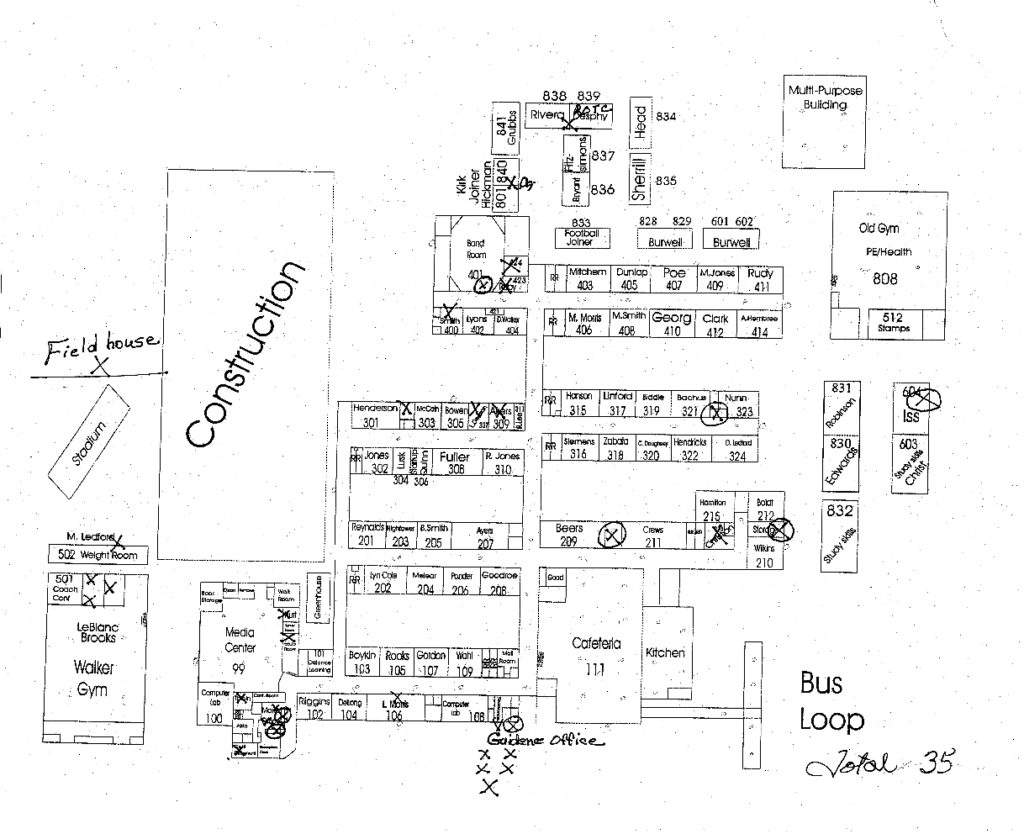 Before image correction
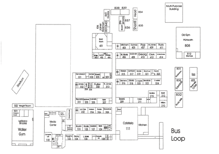 After image correction
What’s Wrong with This Drawing?
At first glance, and from a distance, the original scan may not look too bad but if you look closer, you can see some of the problems. For example, lines are skewed, there are markups obstructing the geometry, and there are specs and smudges making look dirty. See the examples I have listed below.
The entire drawing is slanted right.
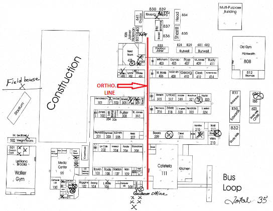 Before image correction
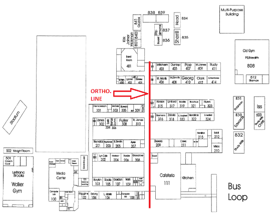 After image correction
There are speckles all over the drawing from the scan process:
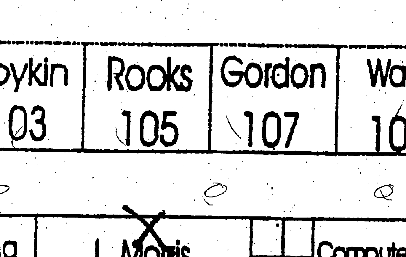 Before image correction
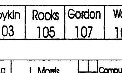 After image correction
And there are handwritten notes that need to be removed: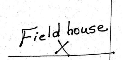
Keep reading to see how I fix the issues listed above.
Save, Save, Save
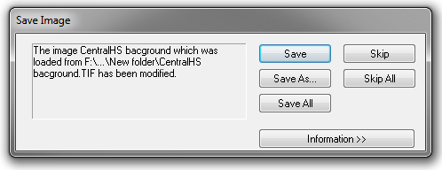
After each step in the sections below I hit save. If you make an image modification, a dialog box will pop up asking to save the image. I always click save here.
Referencing the Image to the Drawing
To get started, I convert the scan to a .tif image, reference it into a DWG, and bring it up to scale using AutoCAD Raster Design. Check out my previous post on Raster Design for details about these tools.
Step 1: Clean up — Deskew
Locate the Cleanup button on the Edit panel in the Raster Tools Tab.

Hit the drop-down menu and click the Deskew button.

Once the command is executed, specify a base point. This point can be anywhere in the drawing.
Next, the command will ask you to Specify source angle. AutoCAD will ask for an angle (or two points). I identify the longest line in the drawing that needs to be orthographic. Then, for the first pick-point, I click an endpoint (on that longest line), and then I pick an endpoint (on the other end of the longest line). AutoCAD will then ask for a destination angle, which is what you want the angle for the line you just picked to be. In my case, I picked a line that should be 90 degrees (straight up) but it wasn’t. I typed in 90 for my destination angle, and this rotated the whole image and corrected the drawing skew. See my previous post on Raster design for more details about fixing image skew.
Step 2: Rubber Sheet
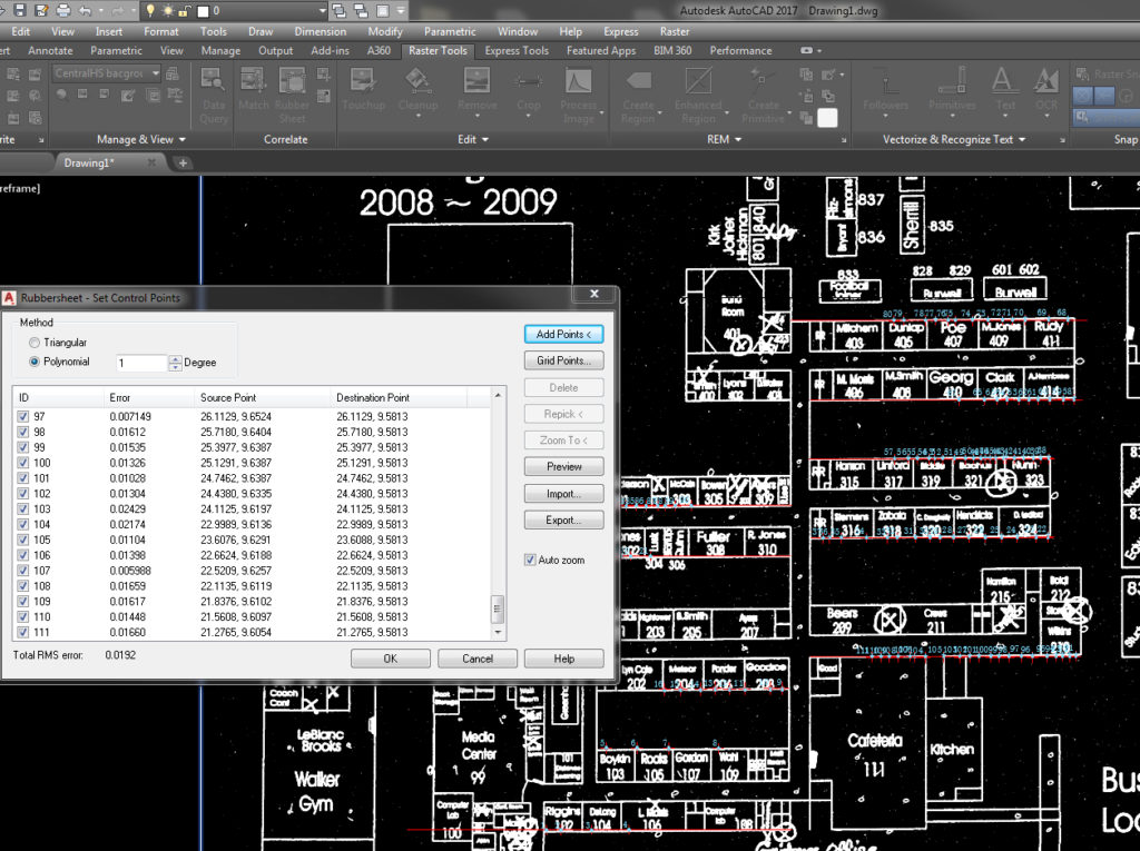
You may notice some of the drawing was fixed but there are other places in the drawing that are not orthogonal. Go back to my second post to see how the rubber sheet can help you with this. Below is a picture of my rubber stamp points for this drawing. The results are subtle when zoomed out, but make a big difference when you zoom in for a closer look.
Step 3: Clean Up — Despeckle
Now that the image is deskewed and rubber sheet stretched into shape, we will use another clean up tool. The Despeckle command does exactly what it sounds like: It despeckles! See all of the speckles in the image below? That’s what we’re about to fix.
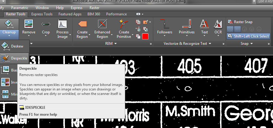
Start by clicking on the Cleanup dropdown menu and select the Despeckle command. Next, you’ll confirm the image you’re selecting. Then you’re asked to pick a speckle to set the size. You also have the option to pick a window over a single speck to define the size of all speckles to remove. I find it best to pick a speckle then zoom out to preview in red that which is being removed from the image. See below for a preview of speckles about to be removed from my drawing.
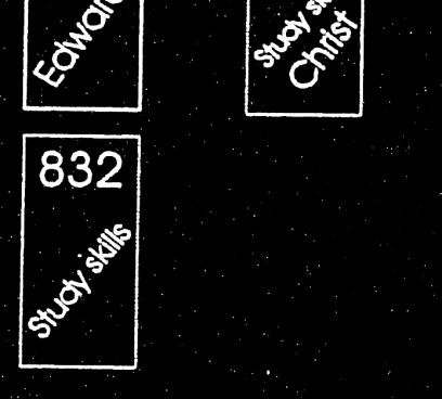 Speckles are present
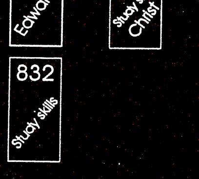 Preview of speckles to be deleted (in red/pink)
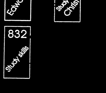 Speckles are gone!
If you see more that you want to take out, you can click again. Just be sure to zoom out and see what the preview looks like and that you will not lose any of the image you were planning on keeping. If the speckle you select gets to be a too big it will remove more than you wanted. We’ll get rid of the bigger ones later in the post.
Time to Get the Eraser Out: Touchup Tool Explained
Now I’ll walk you through the Touchup tool. Essentially, this tool is an eraser. Like in most imaging programs, you click on the image in locations where you want to erase something. First, click the touchup button and the touchup toolbar will pop up. The square brush, circle brush, and rectangle brush buttons determine the shape of the eraser, and the “two points”/paintbrush button changes its size. The black/white button toggles the color the eraser will leave behind.

For the erase functionality, I tap the black/white button to make the black square come forward. This way, the changes I’m about to make will happen in black. Next, I click on the “two points”/paintbrush icon in order to create a pickbox size. This places the pickbox on my curser and I can start selecting the unwanted objects in the drawing. In cleaning up this type of drawing, I’ll change the brush type multiple times in order to get large and small clean-up areas. You can even use this to erase a building out of a drawing if you need to!
The Results
From my point of view, what you see below is a much cleaner product than the original.
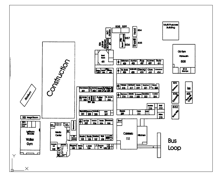
If I have to use a scan as a background for an engineering drawing, I wouldn’t want to do it without AutoCAD Raster Design in my toolbox. This is part of why AutoCAD Raster Design has been a secret weapon of mine for many years, and I hope that now it’ll be one of yours going forward.


