Getting started with AutoCAD? Then let’s start at the very beginning!
The “Beginner’s Guide for CAD Terms” covers some of the basics to help get you going. In this first installment of a two-part series, we will explore AutoCAD definitions for the interface and CAD terminology for navigation. Stay tuned for part two where we will cover geometry and object editing.
Note that all definitions are based on the Windows Operating System and are focused on 2D drafting and design. Links for CAD terms provide deeper information to learn more.
AutoCAD Glossary – Interface CAD Terms
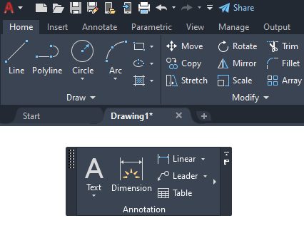
Application Menu – The menu that is displayed when you click the Application button in the upper-left corner of the application window (the large red “A”). The application menu contains common tools for creating, saving, and publishing a file.
Command Line – A text area reserved for keyboard input, prompts, and messages. The Command line can be docked, anchored, or floating within the editor.
Contextual Menu – A ribbon tab that is displayed only when a certain type of object is selected, or when a certain command is started. For example, selecting a hatch or table, or starting the MTEXT command displays a corresponding contextual ribbon.
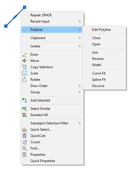
Contextual Popup Menu – A menu accessed by right-clicking on a selected object. The menu contains common commands, along with those that apply to the selected object.
Crosshairs – A type of cursor consisting of two lines that intersect. The AutoCAD crosshairs can be displayed anywhere from 5% of the screen size to 100%.
Drawing Area – Area where drawings are displayed and modified.
Drawing Extents – Smallest rectangular area containing all objects in a drawing.
CUI (Menu) – Generic term for an AutoCAD menu. It is an XML-based file such as acad.cuix that stores customization (menu) data. You modify a customization file through the Customize User Interface Editor. CUIx files replace MNU, MNS, and MNC files that were used to define menus in early releases.
Enterprise CUI – A CUIx file that is typically controlled by a CAD manager. It is often accessed by many users and is stored in a shared network location. The file is read-only to users to prevent the data in the file from being changed. A CAD Manager creates an enterprise CUxI file by modifying a main CUIx file and then saving the file to the support location defined in the Options dialog box, Files tab.
Main CUI File – The CUIx file that defines most of the user interface elements, including the standard menus, toolbars, keyboard accelerators, and so on. The acad.cuix or acadlt.cuix file (the default main CUI file) is automatically loaded when you start the product.
Partial CUI File – Any CUI file that is not defined as the main CUI file. You can load and unload partial CUI files as you need them during a drawing session.
Ribbon – Palette displaying buttons and controls used for both 2D drawing and annotation and 3D modeling, viewing, and rendering.
Ribbon Panel – A set of labeled controls, related to a task, grouped together in a ribbon. Multiple ribbon panels, belonging to one workflow, are grouped together under a ribbon tab
Ribbon Tab – Contains groups of multiple ribbon panels, each belonging to one workflow.
Floating Ribbon Panel – A ribbon panel that is not attached to the rest of the ribbon or file window.
Limits – The user-defined rectangular boundary of the drawing area covered by grid lines (or dots) when the grid is turned on. Also called drawing limits.
Model Space – One of the two primary spaces in which objects reside. Typically, a geometric model is created in model space and drawn at full scale. A layout of specific views and annotations of this model is displayed on a layout in paper space.
Paper Space – One of two primary spaces in which objects reside. Paper space is used for creating a finished layout for printing or plotting, in contrast to drafting or designing. You design your model using the Model tab.
Palette – A user interface element that can be either docked, anchored, or floating in the drawing area. Dockable windows include the Command Line, Status Bar, and Properties palette.
Prompt – A message on the command line or in a tooltip that asks for information or requests an action such as specifying a point.
Snap Grid – An invisible grid that locks the cursor into a specified spacing, which can be different in the X and Y directions. The snap grid does not necessarily correspond to the visible grid, which is controlled separately by GRID.
Snap Angle – The angle that the snap grid is rotated.
Tooltip – A small box of text that identifies or explains an object or interface element when the cursor hovers near or over it.
UCS – A movable coordinate system that establishes the XY plane (work plane) and Z-axis direction for drawing and modeling. You can set the UCS origin and its X, Y, and Z axes to suit your needs.
UCS Icon – Indicates the orientation of the UCS axes.
WCS – Fixed coordinate system that defines the location of all objects and other coordinate systems in a drawing. In new drawings, the user coordinate system (UCS) is initially coincident with the WCS.
Workspace – A named set of menus, toolbars and dockable windows (such as the Properties palette, Design Center, and the Tool palettes window) that are grouped and organized so that you can work in a custom, task-oriented drawing environment.
AutoCAD Glossary – Navigation CAD Terms
File Tab – A tab at the top of the drawing window that corresponds to an open drawing.
Layout Tab – A tab adjacent to the Model Space tab at the bottom of the drawing that provides the 2D environment in which you create layout viewports and place title blocks for plotting. Multiple layouts can be created for each drawing.
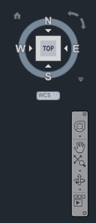
Navigation Bar – Contains navigation tools that are common across multiple Autodesk products. Displayed on the right side of the screen, and below the ViewCube
Pan – To shift the view of a drawing without changing magnification.
ViewCube – A user interface element that displays the current orientation of a model and allows you to interactively rotate the current view or restore a preset view. It is displayed in the upper right corner of the drawing area.
Viewports, Layout – A bounded area that displays a scalable portion of the model space of a drawing that can be moved and resized on a layout.
Viewports, Model – A bounded area that displays some portion of the model space of a drawing that is divided into non-overlapping, tiled sections.
Views – A named and saved graphical representation of a model from a specific location that can be restored later.
Zoom – To reduce or increase the apparent magnification of the drawing area. Accomplished dynamically with the mouse wheel, or via the ZOOM command, which allows various methods such as Extents, All, Object, Previous or Window.
