There’s one thing all CAD drafters have in common. At some point, we’re all beginners. One of the first things we learned about was the Cartesian coordinate system. Y was up, X was across, and 0,0 was your origin point – and always in the lower left. AutoCAD called this the World Coordinate System (WCS), and it gave you a visual cue via a simple icon.
But we beginners soon found that as neat and tidy as the WCS was, the “World” didn’t always play nicely. It’s always shooting off in angles that don’t match our default directions. Or does it? As physical residents of this world, all we have to do to make it all right again is to realign ourselves to match these angles. We can do the same thing in AutoCAD by redefining the WCS into a user-defined coordinate system, or UCS for short.
Now, back in my learning days, setting up a UCS was a bit convoluted and painful. After much evolution, we have a much easier way today. Yes, you can still issue the UCS command and choose options via the command line or dynamic input box, but that can still be rather clunky and sometimes give you results you don’t want.
That simple UCS icon is now an actual object that you can manipulate with modern grips and popup menus. Let’s look at a real-world example of how easy it is to use in your 2D drafting tasks.
Aligning the UCS With Angles in Your Drawing
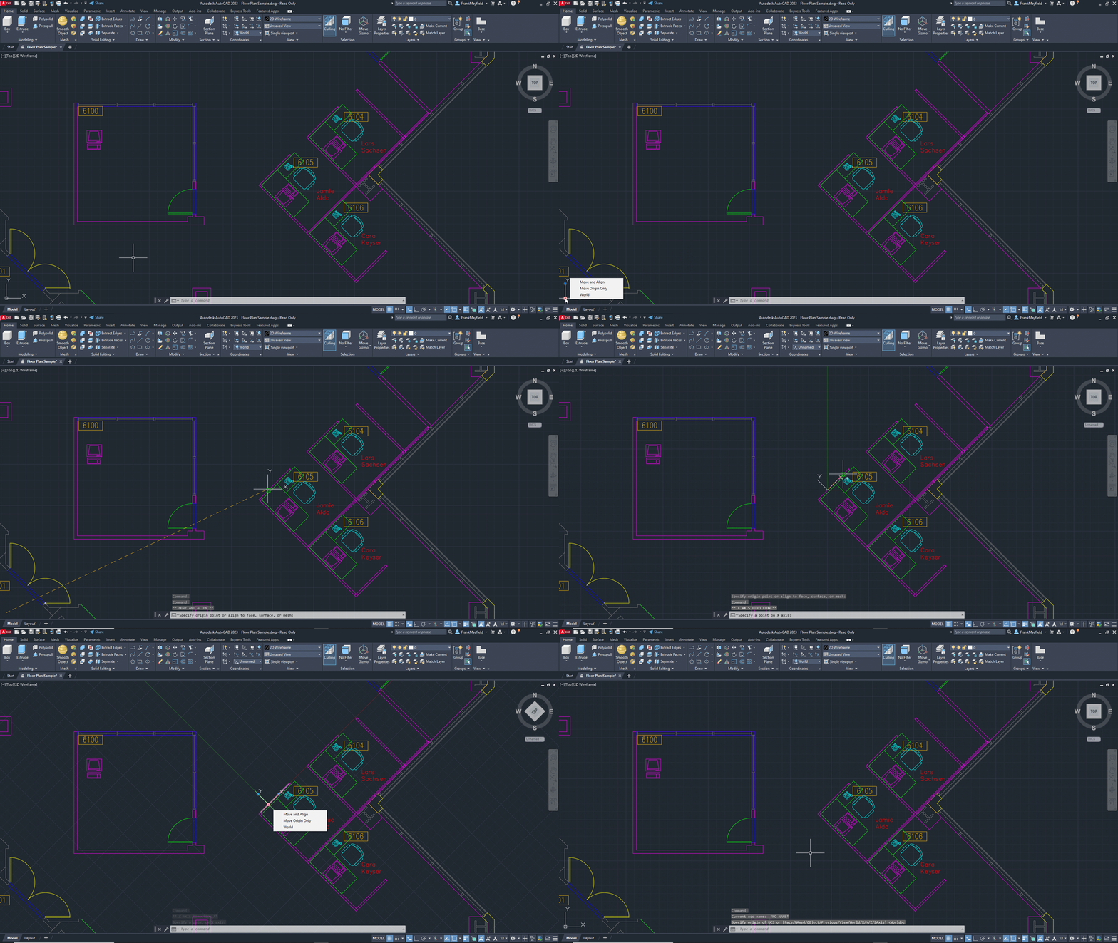
Let’s use AutoCAD’s Floor Plan Sample drawing as our test subject. As you can see, the office labeled 6100 fits nicely into our World Coordinate System. But Jamie, Lars, and Cara’s offices don’t. We have some design work to do around their offices, so it would be nice to be able to draw at those angles easily.

Time for the modern UCS icon to come to our rescue. Remember how I said it was an actual object? Just click on it, and you’ll see its grips light up. Like other multi-functional grips, hovering over them will display a contextual menu of their capabilities – with the top one being the default action. We want to move it and then align it to one of the lines defining Jamie’s office, so we can click the square grip (it turns red, as it is now the “hot” grip) and drag it up and onto Jamie’s outer wall. Remember, the UCS is an object that reacts to Object Snaps, so make sure to use them during this operation.
Now that the icon is attached to the wall, our next step is to align it. This is easy also. Click on the round grip at the end of the X axis and drag it down until you snap onto the line to which we move the icon. That’s it! You’ve done it! Notice that if you have the grid turned on, it too will reflect the new orientation, as does Orthomode.
Now you can complete your design work around the offices with ease. When you’re done and want to return the icon to its default World setting, you just need to hover over the square grip and select World from the popup menu. The icon will reposition itself and return to its default position in the lower left corner.
Give It a Try!
Yes, dear experienced user, there’s more to the UCS command than I’ve described. But for those who are closer to beginners than veterans, I wanted to show them how easy it is to use in their 2D drawings. Perhaps I’ll return to the subject and how easy it is to use in a 3D environment (although slightly different).
So, the next time you find yourself needing to draw at angles other than the default X, Y system, click on the UCS icon and see for yourself how easy it is to redefine it. You’ll become more accurate and efficient, quickly becoming more productive.
More Tuesday Tips
Check out our whole Tuesday Tips series for ideas on how to make AutoCAD work for you. Do you have any favorite AutoCAD tips? Tell us in the comments!


