AutoCAD has a fantastic tool that allows you to import vector-based PDF geometry into an AutoCAD drawing file. Or, if you already have a PDF attached, you can convert its geometry.
Want to learn how to import a PDF into AutoCAD? Getting started is easy—you can find the tool in the Insert tab of the Ribbon, or just type PDFIMPORT on the command line.

Note the command line instructions when you start the command. By default, you’ll get a file selection dialog, but you can also select an existing PDF underlay.

Once you have selected the desired PDF, AutoCAD will display the Import PDF dialog box. There are five distinct sections, and we’ll discuss each of these.
Import PDF Dialog Box
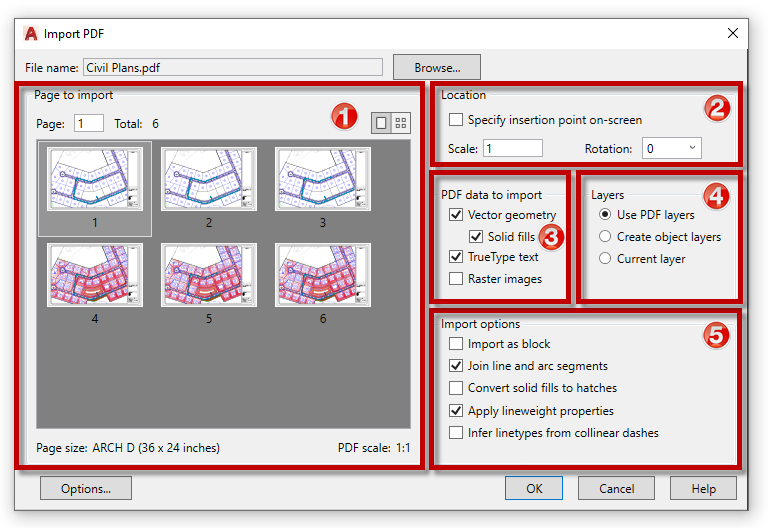
With this image, we’ll go step-by-step through all five components of the Import PDF dialog box in AutoCAD.

The large portion on the left is the Page to Import section. It displays the thumbnail(s) of the PDF file. You can select either single or multi-sheet PDFs to import, but it’s important to note – you can only import one sheet at a time. Enter the sheet number in the Page box or click on the corresponding thumbnail image. Notice also this area displays the page size and the scale of the PDF.
The second section lets you choose between using the default insertion of the PDF or specifying it in the AutoCAD drawing area. You can also pre-set the scale and rotation from here.
Section three is important. At the beginning of this post, I mentioned “vector-based PDF geometry.” Make sure vector geometry is checked to bring in lines, arcs, circles, etc. Also, none of this works on raster-based PDFs. If your PDF was created with a scanner, or some other non-vector software (such as AutoCAD), this tool will not create usable geometry.
The other important selection in this section is the option to import TrueType fonts. I suggest leaving this one checked. The import tool loves TrueType fonts and will import them successfully. It doesn’t love AutoCAD SHX fonts though. You’ll be able to read the text, but each letter will be made up of individual lines.
SPOILER ALERT: We’ll discuss how to manage SHX fonts in an upcoming article!
Next to the PDF Data section is Layers. You can use the layers defined in the PDF (most common), create a new layer for everything to go on. (e.g., “PDF_Geometry”) or place the imported items onto the current layer.
The last section allows you to tailor the import by selecting various options. There are lots of variables that can affect the translation, such as the DPI at creation or mathematical calculations that may skew a horizontal line.
I typically use the defaults of Join Line and Arc Segments and Apply Lineweight Properties. I rarely bring the whole PDF in as a block, nor do I let it try to decide if collinear dashes are real linetypes.
However, I often do have it Convert Solids to Hatches. Unless you’re sure of where and how the PDF was generated (meaning either you or your team made it), you may need to experiment with various import settings to get your best result.
Bonus Tip
If you ever need to edit your raster-based imagery, you should use the Raster Design toolset which is part of an AutoCAD 2021 subscription.
Some Final Thoughts
Since this functionality was added to AutoCAD, it has saved me on numerous occasions. If you’ve worked with AutoCAD for any length of time, no doubt you’ve needed to convert PDFs as well.
Whatever your reason for wanting to import PDF geometry, knowing how to control the translation can greatly improve your final quality.
Join me next time for a companion piece to PDF Import, where we’ll discuss how to recognize and convert AutoCAD’s SHX fonts.


