Wow, was I ever delighted by the responses I received from last week’s gate design challenge! The first correct answer came from Emre Cengizoglu, a MSc civil engineer from Turkey. Emre, who works for a company doing steel projects, started with a reference circle with the radius of the diagonal length, created a 1-1/2” brace with that diagonal, and then used the Align command to place it. Working independently, Brian Lottis with Mazzetti, Inc. out of Portland, and Paul Stilwell, Senior Surveyor and CAD Supervisor with Survey Systems Ltd, out of the United Kingdom, each used the method I had in mind.
First, they each constructed a large circle centered on one corner at P1 and a point on the radius at P2. Next, they drew a line at an arbitrary angle from P3 to P4 on the circle (you can use the near object snap to avoid having to trim or extend the line). They then offset the line by 1-1/2” and trimmed it back to the circle. From there, they used the Rotate command’s Reference option to rotate the diagonal brace into place. The reference points they specified are on a diagonal at P5 and P6, and the final point of rotation was at P7. After trimming the lines, Paul and Brian were done. The precise length of each diagonal edge of the brace was 53.36588038 inches.
Your real-life AutoCAD drawing tips (and lessons learned) for the gate-design challenge
- Create construction geometry when needed: Keep it on a separate layer for later reference, but watch out for extraneous geometry.
- Rotate objects into place: You can use the Reference option to align geometry.
- Get creative: There are always several ways to combine your imagination with AutoCAD tools to solve a geometric problem.
- Be careful: Always check! I received several solutions that were tantalizingly close and deceptively easy. To paraphrase H.L. Mencken, for every problem, there’s a solution that is neat, plausible … and wrong.
Using tangents to close the gate
There are also solutions, using tangents to circles, that weren’t allowed for this exercise. Let’s take a look.
I scaled up the illustrations below so you can see the circles better.
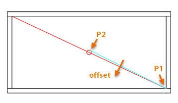
In this illustration, you can see that a diagonal line was created between the inside corners, and a circle of radius 3/4” (or diameter 1-1/2”) was created at the midpoint of the line.
Next, create a line from P1 to the tangent to the circle at P2.
Then, offset that line by 1-1/2” and extend and trim them both into place.
 In the next illustration, Misha Belilovskiy, Senior QA Manager at Autodesk, created a circle of radius 1-1/2” at the inside corner.
He then created a line from P1 to the tangent of the circle at P2. Offsetting the line and trimming the results yielded the precise solution.
Thanks to everyone who worked on this challenge! It was a lot of fun!
AutoCAD Tuesday Tips: The Adventure Continues ….
Last week’s AutoCAD Tuesday Tips with Dieter … Open the Gate — Real-Life AutoCAD Drawing Tips, Part 1
Next week’s AutoCAD Tuesday Tips with Lynn … AutoCAD Right-Click Menu – Find the Hidden Gems
Can’t wait a week for your next tip? Register to download Lynn Allen’s “best of” AutoCAD and AutoCAD LT tips book.


