
Anyone who works in the construction industry is intimately familiar with the different types of construction drawings involved in a project. But can you define the differences between them?
Here's a simple primer for understanding the differences and the roles between different types of drawings. We'll cover:
The term “construction drawings” refers to the collection of final preconstruction drawings that represent the building as a whole. They are the pictorial record of the official design for the building, and generally include detailed depictions of every element of the finished building including the foundation, floor, walls, elevations, interior details and elevations, cabinetry, MEP design, structural details, and ceiling plans.
Construction drawings:
All construction drawings are important, either for the process of construction or for the building’s operators after construction. Understanding the differences can help construction professionals make better use of their documents, and organize them more effectively.
Now that we know the basics of why construction drawings are essential on projects, let's explore the key types.
A site plan (aka plot plan) is a type of construction drawing that provides an overhead view of the entire project site, showing the layout of structures, boundaries, and utilities in relation to the property. It's essentially a map of the project site and details how everything will be positioned on the land before construction begins.
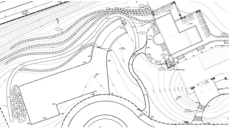
A solid site plan contains key elements such as property lines, existing and proposed structures, access points, utilities, drainage systems, and landscaping features. A legend table also explains the symbols, measurements, and designations used throughout the drawing.
Site plans can be in 2D and 3D. 2D site plans provide a flat, overhead view that focuses on spatial relationships and measurements, while a 3D site plan gives a more realistic, immersive perspective, allowing you to visualize elevations, depths, and the overall design about the surrounding environment.
Site plan drawings:
A floor plan drawing is a detailed, scaled diagram that shows the layout of individual rooms, walls, doors, windows, and other interior elements from a top-down view. It lets you visualize the flow and functionality of a building's interior spaces and shows how different rooms and areas connect to one another. Floor plan drawings allow stakeholders to understand room dimensions, furniture placement, and overall design before construction or remodeling begins.
Some of the key elements that a floor plan drawing contains:
Ideally, it should also have notes on construction materials, finishes, and structural components.
Architects typically produce them because they're responsible for designing the overall layout and structure of buildings. That said, contractors and builders may also produce revised versions or as-built drawings to reflect any changes made during construction.
Floor plan drawings:

Architectural drawings convey detailed information on the structure you're building. It's a broad term that includes various drawings that communicate design concepts, technical details, and construction requirements.
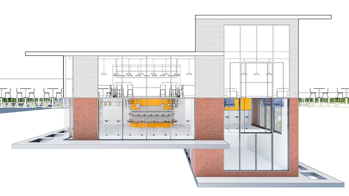
Architectural drawings typically contain information such as dimensions, materials, layouts, and structural elements, ensuring that all aspects of the project are clearly understood and properly executed.
Site plans, floor plans, landscape drawings, excavation drawings, and as-builts are all examples of architectural drawings. Depending on what's being produced, these drawings can come in the form of blueprints, CAD drawings, or 3D renderings. Architectural drawings also include notes, symbols, and a legend to help stakeholders interpret the design accurately.
All drawings must, of course, adhere to building codes, regulations, and standards to ensure compliance with safety and zoning requirements.
Architectural drawings:
Structural drawings show the specifications of a building's structural components—i.e., the load-bearing elements such as beams, columns, foundations, walls, and floors that support the building's stability and integrity. These drawings are meant to outline how these components will be constructed, ensuring the building can withstand various forces such as weight, wind, and seismic activity.
Architects, engineers, and builders rely on structural drawings to accurately design and construct the framework of a building. These drawings are critical to ensuring that all structural elements are installed correctly and comply with safety codes. Structural drawings include details like dimensions, material specifications, load requirements, connection types, and reinforcement details for each structural element.
A few examples of structural drawings are framing plans, steel connection details, vertical sections, cross-sections, and more.
Structural drawings:
MEP drawings convey the mechanical, electrical, and plumbing systems, showing how they should be installed and integrated.
Mechanical drawings focus on heating, ventilation, and air conditioning (HVAC) systems. They contain details like ductwork layouts, equipment locations, and system specifications to ensure proper climate control and air quality.
On the other hand, electrical drawings focus on the building's electrical system, including power distribution, lighting, and communication systems. They contain wiring diagrams, circuit layouts, outlet and switch locations, and electrical panel specifications.
Meanwhile, plumbing drawings illustrate the water supply, drainage, and waste removal systems and contain pipe layouts, fixture locations, pipe sizing, and material specifications to ensure efficient water flow and sanitation.
Other types of MEP drawings include fire protection drawings, MEP shop drawings, pipe spool drawings, and more.
MEP drawings:
Fire protection drawings are essential for ensuring the building adheres to safety codes and regulations, and are often included in the MEP drawings as mentioned above. These include:
Fire protection drawings are critical for ensuring the safety of the building’s occupants and meeting fire code regulations.
The term “shop drawings” refers to drawings that are created by the contractor, subcontractors, and/or prefab vendors to further define the design of specific building components. They are most frequently created for MEP components of the building, but can also be created to show fine details of cabinetry and other elements. Shop drawings are necessary for planning the prefabricated components of a building, and as such have become more numerous as the use of prefab and modular construction technology has become more common.
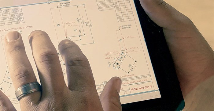
Shop drawings are created prior to construction, and are agreed upon by the design team, owners, contractors, and subs before work begins. They are not usually a part of the official contract documents, and may occasionally be produced during the course of construction as necessary.
Shop drawings:
The term “as-built drawings” refers to drawings that depict the building and all its components as they were actually constructed. Construction is complex and every project encounters unexpected obstacles and conditions that alter the plans.
As-built drawings are a set of drawings that represent the final exact construction of the building, including all materials, components, locations, dimensions, and other details of every element of the building. They are produced by the contractor and subcontractors after completion of the project.
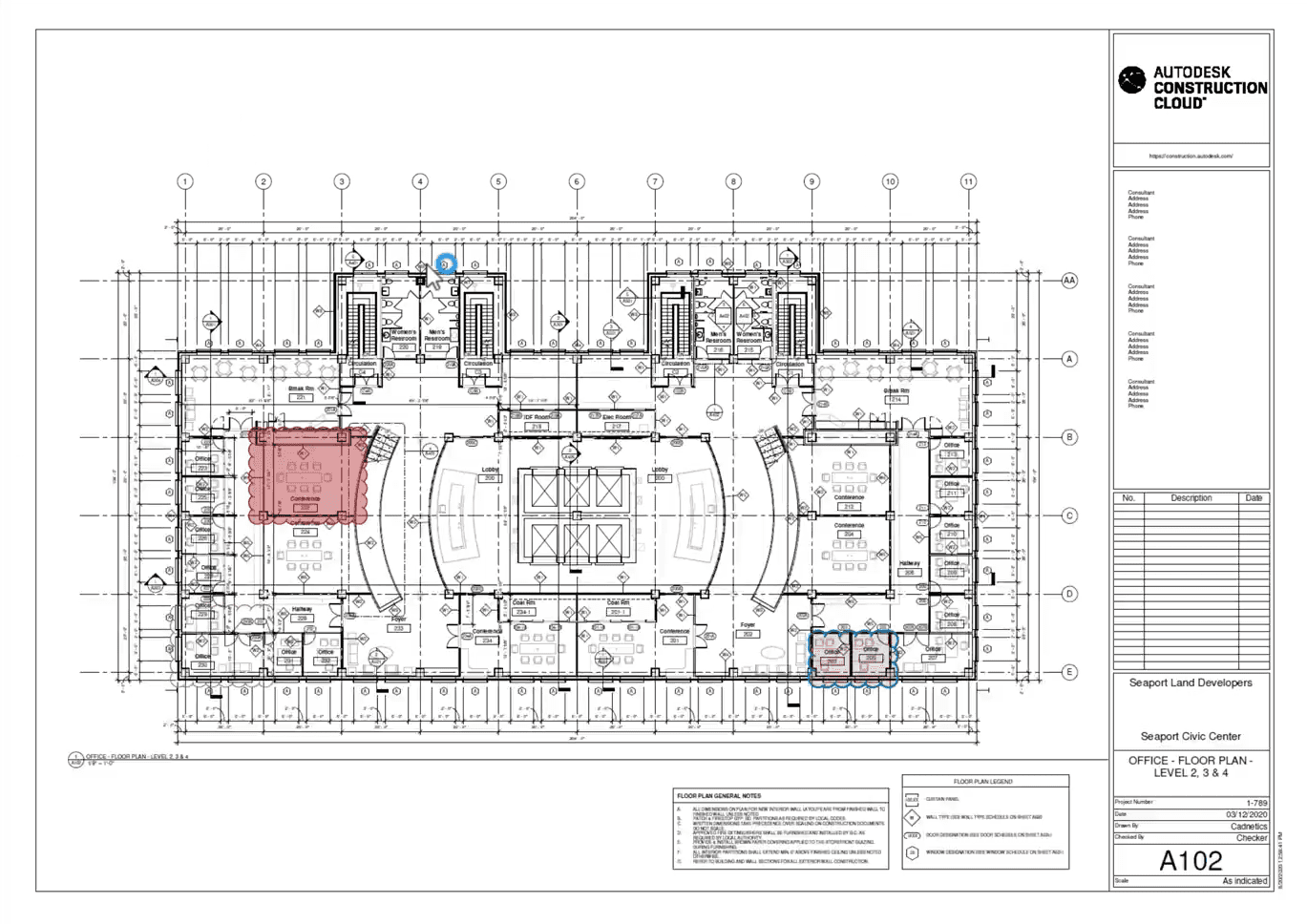
As-built drawings are useful to building owners for maintenance, safety, repairs, updates, and renovations. Traditionally, they are created from the final redlined version of the original construction drawings and are time-consuming to produce. Today’s technology makes it possible to produce and share as-built drawings quickly and more accurately than ever, thanks to the ability to update construction drawings in real time as the project proceeds.
As-Built Drawings:
All these types of construction drawings are important, either for the process of construction or for the building’s operators after construction. Understanding the differences can help construction professionals make better use of their documents, and organize them more effectively.
Interested in streamlining your document management? Learn more about Document Management in Autodesk Construction Cloud.

