Working with large assemblies in Inventor can get complex. Let’s dive into 10 tips that will help you work more efficiently.
Large assemblies in Inventor
As designs become larger and more complex, they consume more computing time. As a result, you may notice your load times are increasing as your assembly grows. You may even receive out of memory errors, experience poor graphics performance, or it takes entirely too long to create your drawing views and annotations.
Why is this happening? Well, it can be due to a number of reasons including:
Number of component occurrences – Do you have several copies or several references to a part of assembly, but only one reference to that unique part or subassembly?
Number of unique files – How many files are unique?
Part complexity – How much feature complexity do you add to your models?
Heavy data from your supply chain – Are you brining in heavy data from other CAD systems from your suppliers or customers?
Hardware configuration – Have you considered changing your RAM, hard disc speed, processor and video card?
Tips for managing large assemblies in Inventor
Let’s dive into some common scenarios and top tips for working with large assemblies in Inventor.
Model complexity
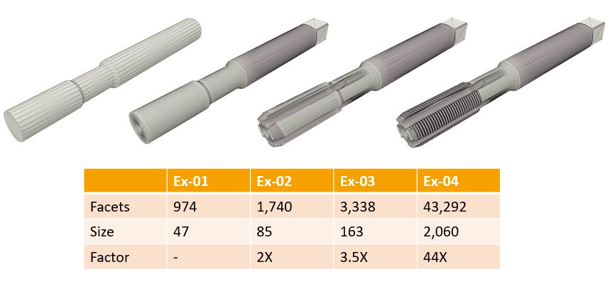
It’s natural to want to add as much detail as possible when creating parts. However, do you really need all of that detail in the main assembly as you are working? What exactly is the impact of adding a lot of detail? Take the part above as an example: observe the progression of adding features to the part. You can see the highly simplified part on the left and the impact at each stage of adding new 3D modeling features. Complexity doesn’t increase significantly until you begin adding numerous faces, such as with a helicoil cut or extruded text. The part is not just four times larger; it can become 50 times larger. So, consider the impact of some of the features you are adding to your parts and take into account the best practices that will give you the results you are looking for.
Model states
When you need very complex features for operations, model states can be a great solution. It’s an excellent way to manage parts that have both machined and casted versions. It is also useful for families of parts, such as different sizes of fasteners, or for quickly displaying sheet metal folding operations in a model or drawing view. Model states help with alternate assembly positions, like an air cylinder that is extended or retracted. Model states can also be used to simplify parts or subassemblies. When you create a simplified model state, it can then represent that simplified version in the main assembly or subassembly.
Model states and drawing views
When referring to model states in drawings there are a few things to look out for. For instance, you can display different model states per view, which is a great option when you need it. However, when your assemblies become very large, you may want to handle this differently, as each model state used in a drawing act like a copy of the data. Instead of using model states for different views, consider using different view representations or create a separate drawing for each model state. This approach can help manage data size and complexity more effectively.
Simplify
Use the Simplify command to reduce the number and cost of components in large assemblies. There have been some great enhancements to the Simplify command and user interface. Within the command, there is an option to create a substitute part, which is a fantastic tool for collaborating with customers on various types of projects, including BIM model creation. Substitutes can also be an excellent way to simplify an assembly, resulting in a simplified part that remains associative to the assembly or subassembly it was derived from. It is not necessarily recommended to create substitutes early in the design process when heavy design work is ongoing. It’s more common to do this later when the design is near completion.
Adaptivity
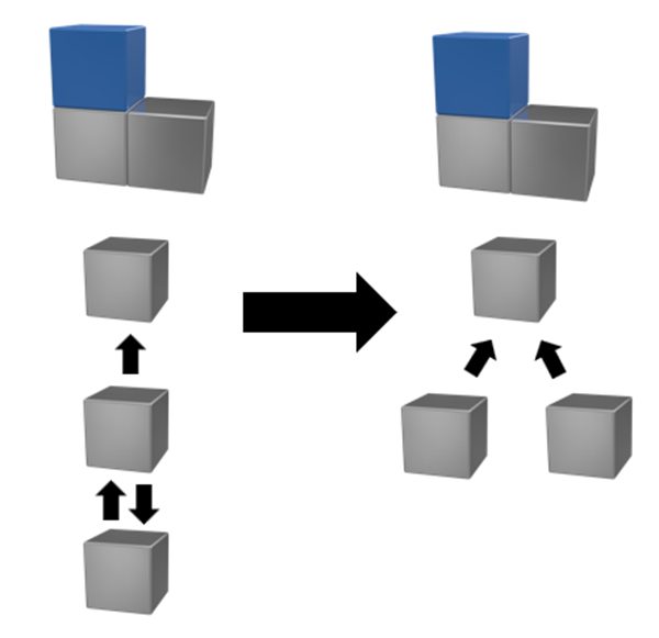
Adaptivity is a valuable method for designing around other components in an assembly environment. It allows you to associate elements like hole alignment or general relationships that are maintained from one part to another. However, in a large assembly environment, it’s recommended to avoid overusing adaptivity. Keep in mind that the relationships created between components must periodically recalculate, which can impact performance. If you do use adaptivity, make sure that your parts are related to a top-level component. As shown in the image on the right, avoid cascading relationships where Part C relates to Part B, and Part B relates to Part A. Additionally, try to avoid cyclic relationships between components where two features are related to each other. When adaptive relationships are not a concern, it makes sense to turn adaptivity off.
Assembly structure
Next, let’s look at your assembly browser and examine how you are structuring your assemblies. Are you taking advantage of the benefits of using subassemblies? It’s best practice to combine parts into subassemblies because this results in fewer top-level constraints that need to be calculated. The constraints within a subassembly do not have to be recalculated at the top level; they can be assumed to be calculated the same as a rigid object, unless you decide to change the subassembly to flexible. You can also have subassemblies inside subassemblies, with the depth being up to you. Generally, it is advised not to go too deep, but doing so should not affect performance.
Assembly constraints
With constraints, it’s important to fully define the location of your components as much as possible to reduce the degrees of freedom in your design. Even more crucially, if you over-define components, make sure to resolve the conflicts as you work, as conflicting constraints will impact performance. You can fix errors manually or use tools such as the Design Doctor to guide you through the process of editing, deleting, or suppressing constraints. Additionally, you can right-click on a constraint with a warning to find the Recover tool, which can help address the issue.
Express mode
Let’s talk about express mode. What is it? Usually, when you open an assembly, it fully loads all of the component data into memory. For large assemblies, you can open them in express mode, where only the component cached graphics are loaded into memory. This cached graphics data is saved from the fully loaded model, allowing you to use express mode later, which enables you to load your assemblies several times faster. So, why not open everything in express mode? The reason comes down to what you want to do when it’s open. You can do a lot in express mode, especially with recent enhancements, but some features will require you to fully load the model. You may notice that models are automatically loaded based on the features or commands you are using, which is an on-demand load workflow and a big improvement from the early phases of express mode.
Remember that express mode was released nine years ago, and a lot has changed since then. Significant work has been done to improve the experience, so if you haven’t used it in a while, it would be worth looking into the enhancements made by the Inventor development team. One last thing: if your team is using express mode, make sure you are all using the same settings for consistency.
In express mode, you can place components, add constraints or joints, create and edit components in place, use section view, create and edit work features, pattern a component, copy or mirror a component, and manage assemblies and representations.
Folder structure
As you know, the parts and subassemblies are reference files that need to be stored and maintained. What is the best way to save those files? A flat folder structure works best when possible, where you save all files in one folder. This approach makes it easier for Windows to find referenced files in the main assembly. Some designers follow this method, while others may find it impractical and use subfolders instead. The idea is to make that subfolder structure as flat as possible. Another rule of thumb is to keep the number of parts in a folder to 800 or less. Additionally, there is a Windows limit of 10,000 files in one folder.
Project files and libraries
There are a number of things you can do with projects and libraries to optimize your workflow. Set the Included File path option to point to a single, read-only project file maintained on the network by the CAD administrator, and make sure all users have access to that project file. Never locate a workspace on a network location; it is best practice to open your models and drawings from a local directory instead of a network.
Additionally, avoid cross-referencing workspaces or library locations with another workgroup, as mapped network drives can slow down the machine’s ability to open and save files due to Windows attempting to resolve these every time. Keep the relative paths set to true, meaning paths should be relative to the location of the project file. The fewer workgroup search paths defined, the better, as fewer search paths improve file searches. If your projects require portability, be sure to define all storage locations as subfolders of a project folder, which contains only the project file.
And there you have it, 10 ways to make working with large assemblies in Inventor less stressful. Keep your eye out for more tips on this topic coming soon.
Enhance Your Engineering Workflows
Precise, powerful, and ready for innovation with Autodesk Inventor.
Your privacy is important to us and so is an optimal experience. To help us customize information and build applications, we collect data about your use of this site.
Learn more about the Third-Party Services we use in each category, and how we use the data we collect from you online.
Strictly necessary – required for our site to work and to provide services to you
Qualtrics
We use Qualtrics to let you give us feedback via surveys or online forms. You may be randomly selected to participate in a survey, or you can actively decide to give us feedback. We collect data to better understand what actions you took before filling out a survey. This helps us troubleshoot issues you may have experienced. Qualtrics Privacy Policy
Akamai mPulse
We use Akamai mPulse to collect data about your behavior on our sites. This may include pages you’ve visited, trials you’ve initiated, videos you’ve played, purchases you’ve made, your IP address or device ID, and your Autodesk ID. We use this data to measure our site performance and evaluate the ease of your online experience, so we can enhance our features. We also use advanced analytics methods to optimize your experience with email, customer support, and sales. Akamai mPulse Privacy Policy
Digital River
We use Digital River to collect data about your behavior on our sites. This may include pages you’ve visited, trials you’ve initiated, videos you’ve played, purchases you’ve made, your IP address or device ID, and your Autodesk ID. We use this data to measure our site performance and evaluate the ease of your online experience, so we can enhance our features. We also use advanced analytics methods to optimize your experience with email, customer support, and sales. Digital River Privacy Policy
Dynatrace
We use Dynatrace to collect data about your behavior on our sites. This may include pages you’ve visited, trials you’ve initiated, videos you’ve played, purchases you’ve made, your IP address or device ID, and your Autodesk ID. We use this data to measure our site performance and evaluate the ease of your online experience, so we can enhance our features. We also use advanced analytics methods to optimize your experience with email, customer support, and sales. Dynatrace Privacy Policy
Khoros
We use Khoros to collect data about your behavior on our sites. This may include pages you’ve visited, trials you’ve initiated, videos you’ve played, purchases you’ve made, your IP address or device ID, and your Autodesk ID. We use this data to measure our site performance and evaluate the ease of your online experience, so we can enhance our features. We also use advanced analytics methods to optimize your experience with email, customer support, and sales. Khoros Privacy Policy
Launch Darkly
We use Launch Darkly to collect data about your behavior on our sites. This may include pages you’ve visited, trials you’ve initiated, videos you’ve played, purchases you’ve made, your IP address or device ID, and your Autodesk ID. We use this data to measure our site performance and evaluate the ease of your online experience, so we can enhance our features. We also use advanced analytics methods to optimize your experience with email, customer support, and sales. Launch Darkly Privacy Policy
New Relic
We use New Relic to collect data about your behavior on our sites. This may include pages you’ve visited, trials you’ve initiated, videos you’ve played, purchases you’ve made, your IP address or device ID, and your Autodesk ID. We use this data to measure our site performance and evaluate the ease of your online experience, so we can enhance our features. We also use advanced analytics methods to optimize your experience with email, customer support, and sales. New Relic Privacy Policy
Salesforce Live Agent
We use Salesforce Live Agent to collect data about your behavior on our sites. This may include pages you’ve visited, trials you’ve initiated, videos you’ve played, purchases you’ve made, your IP address or device ID, and your Autodesk ID. We use this data to measure our site performance and evaluate the ease of your online experience, so we can enhance our features. We also use advanced analytics methods to optimize your experience with email, customer support, and sales. Salesforce Live Agent Privacy Policy
Wistia
We use Wistia to collect data about your behavior on our sites. This may include pages you’ve visited, trials you’ve initiated, videos you’ve played, purchases you’ve made, your IP address or device ID, and your Autodesk ID. We use this data to measure our site performance and evaluate the ease of your online experience, so we can enhance our features. We also use advanced analytics methods to optimize your experience with email, customer support, and sales. Wistia Privacy Policy
Tealium
We use Tealium to collect data about your behavior on our sites. This may include pages you’ve visited, trials you’ve initiated, videos you’ve played, purchases you’ve made, and your IP address or device ID. We use this data to measure our site performance and evaluate the ease of your online experience, so we can enhance our features. We also use advanced analytics methods to optimize your experience with email, customer support, and sales. Tealium Privacy Policy
Upsellit
We use Upsellit to collect data about your behavior on our sites. This may include pages you’ve visited, trials you’ve initiated, videos you’ve played, purchases you’ve made, and your IP address or device ID. We use this data to measure our site performance and evaluate the ease of your online experience, so we can enhance our features. We also use advanced analytics methods to optimize your experience with email, customer support, and sales. Upsellit Privacy Policy
CJ Affiliates
We use CJ Affiliates to collect data about your behavior on our sites. This may include pages you’ve visited, trials you’ve initiated, videos you’ve played, purchases you’ve made, and your IP address or device ID. We use this data to measure our site performance and evaluate the ease of your online experience, so we can enhance our features. We also use advanced analytics methods to optimize your experience with email, customer support, and sales. CJ Affiliates Privacy Policy
Commission Factory
We use Commission Factory to collect data about your behavior on our sites. This may include pages you’ve visited, trials you’ve initiated, videos you’ve played, purchases you’ve made, and your IP address or device ID. We use this data to measure our site performance and evaluate the ease of your online experience, so we can enhance our features. We also use advanced analytics methods to optimize your experience with email, customer support, and sales. Commission Factory Privacy Policy
Google Analytics (Strictly Necessary)
We use Google Analytics (Strictly Necessary) to collect data about your behavior on our sites. This may include pages you’ve visited, trials you’ve initiated, videos you’ve played, purchases you’ve made, your IP address or device ID, and your Autodesk ID. We use this data to measure our site performance and evaluate the ease of your online experience, so we can enhance our features. We also use advanced analytics methods to optimize your experience with email, customer support, and sales. Google Analytics (Strictly Necessary) Privacy Policy
Typepad Stats
We use Typepad Stats to collect data about your behaviour on our sites. This may include pages you’ve visited. We use this data to measure our site performance and evaluate the ease of your online experience, so we can enhance our platform to provide the most relevant content. This allows us to enhance your overall user experience. Typepad Stats Privacy Policy
Geo Targetly
We use Geo Targetly to direct website visitors to the most appropriate web page and/or serve tailored content based on their location. Geo Targetly uses the IP address of a website visitor to determine the approximate location of the visitor’s device. This helps ensure that the visitor views content in their (most likely) local language.Geo Targetly Privacy Policy
SpeedCurve
We use SpeedCurve to monitor and measure the performance of your website experience by measuring web page load times as well as the responsiveness of subsequent elements such as images, scripts, and text.SpeedCurve Privacy Policy
Qualified
Qualified is the Autodesk Live Chat agent platform. This platform provides services to allow our customers to communicate in real-time with Autodesk support. We may collect unique ID for specific browser sessions during a chat. Qualified Privacy Policy
Improve your experience – allows us to show you what is relevant to you
Google Optimize
We use Google Optimize to test new features on our sites and customize your experience of these features. To do this, we collect behavioral data while you’re on our sites. This data may include pages you’ve visited, trials you’ve initiated, videos you’ve played, purchases you’ve made, your IP address or device ID, your Autodesk ID, and others. You may experience a different version of our sites based on feature testing, or view personalized content based on your visitor attributes. Google Optimize Privacy Policy
ClickTale
We use ClickTale to better understand where you may encounter difficulties with our sites. We use session recording to help us see how you interact with our sites, including any elements on our pages. Your Personally Identifiable Information is masked and is not collected. ClickTale Privacy Policy
OneSignal
We use OneSignal to deploy digital advertising on sites supported by OneSignal. Ads are based on both OneSignal data and behavioral data that we collect while you’re on our sites. The data we collect may include pages you’ve visited, trials you’ve initiated, videos you’ve played, purchases you’ve made, and your IP address or device ID. This information may be combined with data that OneSignal has collected from you. We use the data that we provide to OneSignal to better customize your digital advertising experience and present you with more relevant ads. OneSignal Privacy Policy
Optimizely
We use Optimizely to test new features on our sites and customize your experience of these features. To do this, we collect behavioral data while you’re on our sites. This data may include pages you’ve visited, trials you’ve initiated, videos you’ve played, purchases you’ve made, your IP address or device ID, your Autodesk ID, and others. You may experience a different version of our sites based on feature testing, or view personalized content based on your visitor attributes. Optimizely Privacy Policy
Amplitude
We use Amplitude to test new features on our sites and customize your experience of these features. To do this, we collect behavioral data while you’re on our sites. This data may include pages you’ve visited, trials you’ve initiated, videos you’ve played, purchases you’ve made, your IP address or device ID, your Autodesk ID, and others. You may experience a different version of our sites based on feature testing, or view personalized content based on your visitor attributes. Amplitude Privacy Policy
Snowplow
We use Snowplow to collect data about your behavior on our sites. This may include pages you’ve visited, trials you’ve initiated, videos you’ve played, purchases you’ve made, your IP address or device ID, and your Autodesk ID. We use this data to measure our site performance and evaluate the ease of your online experience, so we can enhance our features. We also use advanced analytics methods to optimize your experience with email, customer support, and sales. Snowplow Privacy Policy
UserVoice
We use UserVoice to collect data about your behaviour on our sites. This may include pages you’ve visited. We use this data to measure our site performance and evaluate the ease of your online experience, so we can enhance our platform to provide the most relevant content. This allows us to enhance your overall user experience. UserVoice Privacy Policy
Clearbit
Clearbit allows real-time data enrichment to provide a personalized and relevant experience to our customers. The data we collect may include pages you’ve visited, trials you’ve initiated, videos you’ve played, purchases you’ve made, and your IP address or device ID.Clearbit Privacy Policy
YouTube
YouTube is a video sharing platform which allows users to view and share embedded videos on our websites. YouTube provides viewership metrics on video performance. YouTube Privacy Policy
Customize your advertising – permits us to offer targeted advertising to you
Adobe Analytics
We use Adobe Analytics to collect data about your behavior on our sites. This may include pages you’ve visited, trials you’ve initiated, videos you’ve played, purchases you’ve made, your IP address or device ID, and your Autodesk ID. We use this data to measure our site performance and evaluate the ease of your online experience, so we can enhance our features. We also use advanced analytics methods to optimize your experience with email, customer support, and sales. Adobe Analytics Privacy Policy
Google Analytics (Web Analytics)
We use Google Analytics (Web Analytics) to collect data about your behavior on our sites. This may include pages you’ve visited, trials you’ve initiated, videos you’ve played, purchases you’ve made, and your IP address or device ID. We use this data to measure our site performance and evaluate the ease of your online experience, so we can enhance our features. We also use advanced analytics methods to optimize your experience with email, customer support, and sales. Google Analytics (Web Analytics) Privacy Policy
AdWords
We use AdWords to deploy digital advertising on sites supported by AdWords. Ads are based on both AdWords data and behavioral data that we collect while you’re on our sites. The data we collect may include pages you’ve visited, trials you’ve initiated, videos you’ve played, purchases you’ve made, and your IP address or device ID. This information may be combined with data that AdWords has collected from you. We use the data that we provide to AdWords to better customize your digital advertising experience and present you with more relevant ads. AdWords Privacy Policy
Marketo
We use Marketo to send you more timely and relevant email content. To do this, we collect data about your online behavior and your interaction with the emails we send. Data collected may include pages you’ve visited, trials you’ve initiated, videos you’ve played, purchases you’ve made, your IP address or device ID, email open rates, links clicked, and others. We may combine this data with data collected from other sources to offer you improved sales or customer service experiences, as well as more relevant content based on advanced analytics processing. Marketo Privacy Policy
Doubleclick
We use Doubleclick to deploy digital advertising on sites supported by Doubleclick. Ads are based on both Doubleclick data and behavioral data that we collect while you’re on our sites. The data we collect may include pages you’ve visited, trials you’ve initiated, videos you’ve played, purchases you’ve made, and your IP address or device ID. This information may be combined with data that Doubleclick has collected from you. We use the data that we provide to Doubleclick to better customize your digital advertising experience and present you with more relevant ads. Doubleclick Privacy Policy
HubSpot
We use HubSpot to send you more timely and relevant email content. To do this, we collect data about your online behavior and your interaction with the emails we send. Data collected may include pages you’ve visited, trials you’ve initiated, videos you’ve played, purchases you’ve made, your IP address or device ID, email open rates, links clicked, and others. HubSpot Privacy Policy
Twitter
We use Twitter to deploy digital advertising on sites supported by Twitter. Ads are based on both Twitter data and behavioral data that we collect while you’re on our sites. The data we collect may include pages you’ve visited, trials you’ve initiated, videos you’ve played, purchases you’ve made, and your IP address or device ID. This information may be combined with data that Twitter has collected from you. We use the data that we provide to Twitter to better customize your digital advertising experience and present you with more relevant ads. Twitter Privacy Policy
Facebook
We use Facebook to deploy digital advertising on sites supported by Facebook. Ads are based on both Facebook data and behavioral data that we collect while you’re on our sites. The data we collect may include pages you’ve visited, trials you’ve initiated, videos you’ve played, purchases you’ve made, and your IP address or device ID. This information may be combined with data that Facebook has collected from you. We use the data that we provide to Facebook to better customize your digital advertising experience and present you with more relevant ads. Facebook Privacy Policy
LinkedIn
We use LinkedIn to deploy digital advertising on sites supported by LinkedIn. Ads are based on both LinkedIn data and behavioral data that we collect while you’re on our sites. The data we collect may include pages you’ve visited, trials you’ve initiated, videos you’ve played, purchases you’ve made, and your IP address or device ID. This information may be combined with data that LinkedIn has collected from you. We use the data that we provide to LinkedIn to better customize your digital advertising experience and present you with more relevant ads. LinkedIn Privacy Policy
Yahoo! Japan
We use Yahoo! Japan to deploy digital advertising on sites supported by Yahoo! Japan. Ads are based on both Yahoo! Japan data and behavioral data that we collect while you’re on our sites. The data we collect may include pages you’ve visited, trials you’ve initiated, videos you’ve played, purchases you’ve made, and your IP address or device ID. This information may be combined with data that Yahoo! Japan has collected from you. We use the data that we provide to Yahoo! Japan to better customize your digital advertising experience and present you with more relevant ads. Yahoo! Japan Privacy Policy
Naver
We use Naver to deploy digital advertising on sites supported by Naver. Ads are based on both Naver data and behavioral data that we collect while you’re on our sites. The data we collect may include pages you’ve visited, trials you’ve initiated, videos you’ve played, purchases you’ve made, and your IP address or device ID. This information may be combined with data that Naver has collected from you. We use the data that we provide to Naver to better customize your digital advertising experience and present you with more relevant ads. Naver Privacy Policy
Quantcast
We use Quantcast to deploy digital advertising on sites supported by Quantcast. Ads are based on both Quantcast data and behavioral data that we collect while you’re on our sites. The data we collect may include pages you’ve visited, trials you’ve initiated, videos you’ve played, purchases you’ve made, and your IP address or device ID. This information may be combined with data that Quantcast has collected from you. We use the data that we provide to Quantcast to better customize your digital advertising experience and present you with more relevant ads. Quantcast Privacy Policy
Call Tracking
We use Call Tracking to provide customized phone numbers for our campaigns. This gives you faster access to our agents and helps us more accurately evaluate our performance. We may collect data about your behavior on our sites based on the phone number provided. Call Tracking Privacy Policy
Wunderkind
We use Wunderkind to deploy digital advertising on sites supported by Wunderkind. Ads are based on both Wunderkind data and behavioral data that we collect while you’re on our sites. The data we collect may include pages you’ve visited, trials you’ve initiated, videos you’ve played, purchases you’ve made, and your IP address or device ID. This information may be combined with data that Wunderkind has collected from you. We use the data that we provide to Wunderkind to better customize your digital advertising experience and present you with more relevant ads. Wunderkind Privacy Policy
ADC Media
We use ADC Media to deploy digital advertising on sites supported by ADC Media. Ads are based on both ADC Media data and behavioral data that we collect while you’re on our sites. The data we collect may include pages you’ve visited, trials you’ve initiated, videos you’ve played, purchases you’ve made, and your IP address or device ID. This information may be combined with data that ADC Media has collected from you. We use the data that we provide to ADC Media to better customize your digital advertising experience and present you with more relevant ads. ADC Media Privacy Policy
AgrantSEM
We use AgrantSEM to deploy digital advertising on sites supported by AgrantSEM. Ads are based on both AgrantSEM data and behavioral data that we collect while you’re on our sites. The data we collect may include pages you’ve visited, trials you’ve initiated, videos you’ve played, purchases you’ve made, and your IP address or device ID. This information may be combined with data that AgrantSEM has collected from you. We use the data that we provide to AgrantSEM to better customize your digital advertising experience and present you with more relevant ads. AgrantSEM Privacy Policy
Bidtellect
We use Bidtellect to deploy digital advertising on sites supported by Bidtellect. Ads are based on both Bidtellect data and behavioral data that we collect while you’re on our sites. The data we collect may include pages you’ve visited, trials you’ve initiated, videos you’ve played, purchases you’ve made, and your IP address or device ID. This information may be combined with data that Bidtellect has collected from you. We use the data that we provide to Bidtellect to better customize your digital advertising experience and present you with more relevant ads. Bidtellect Privacy Policy
Bing
We use Bing to deploy digital advertising on sites supported by Bing. Ads are based on both Bing data and behavioral data that we collect while you’re on our sites. The data we collect may include pages you’ve visited, trials you’ve initiated, videos you’ve played, purchases you’ve made, and your IP address or device ID. This information may be combined with data that Bing has collected from you. We use the data that we provide to Bing to better customize your digital advertising experience and present you with more relevant ads. Bing Privacy Policy
G2Crowd
We use G2Crowd to deploy digital advertising on sites supported by G2Crowd. Ads are based on both G2Crowd data and behavioral data that we collect while you’re on our sites. The data we collect may include pages you’ve visited, trials you’ve initiated, videos you’ve played, purchases you’ve made, and your IP address or device ID. This information may be combined with data that G2Crowd has collected from you. We use the data that we provide to G2Crowd to better customize your digital advertising experience and present you with more relevant ads. G2Crowd Privacy Policy
NMPI Display
We use NMPI Display to deploy digital advertising on sites supported by NMPI Display. Ads are based on both NMPI Display data and behavioral data that we collect while you’re on our sites. The data we collect may include pages you’ve visited, trials you’ve initiated, videos you’ve played, purchases you’ve made, and your IP address or device ID. This information may be combined with data that NMPI Display has collected from you. We use the data that we provide to NMPI Display to better customize your digital advertising experience and present you with more relevant ads. NMPI Display Privacy Policy
VK
We use VK to deploy digital advertising on sites supported by VK. Ads are based on both VK data and behavioral data that we collect while you’re on our sites. The data we collect may include pages you’ve visited, trials you’ve initiated, videos you’ve played, purchases you’ve made, and your IP address or device ID. This information may be combined with data that VK has collected from you. We use the data that we provide to VK to better customize your digital advertising experience and present you with more relevant ads. VK Privacy Policy
Adobe Target
We use Adobe Target to test new features on our sites and customize your experience of these features. To do this, we collect behavioral data while you’re on our sites. This data may include pages you’ve visited, trials you’ve initiated, videos you’ve played, purchases you’ve made, your IP address or device ID, your Autodesk ID, and others. You may experience a different version of our sites based on feature testing, or view personalized content based on your visitor attributes. Adobe Target Privacy Policy
Google Analytics (Advertising)
We use Google Analytics (Advertising) to deploy digital advertising on sites supported by Google Analytics (Advertising). Ads are based on both Google Analytics (Advertising) data and behavioral data that we collect while you’re on our sites. The data we collect may include pages you’ve visited, trials you’ve initiated, videos you’ve played, purchases you’ve made, and your IP address or device ID. This information may be combined with data that Google Analytics (Advertising) has collected from you. We use the data that we provide to Google Analytics (Advertising) to better customize your digital advertising experience and present you with more relevant ads. Google Analytics (Advertising) Privacy Policy
Trendkite
We use Trendkite to deploy digital advertising on sites supported by Trendkite. Ads are based on both Trendkite data and behavioral data that we collect while you’re on our sites. The data we collect may include pages you’ve visited, trials you’ve initiated, videos you’ve played, purchases you’ve made, and your IP address or device ID. This information may be combined with data that Trendkite has collected from you. We use the data that we provide to Trendkite to better customize your digital advertising experience and present you with more relevant ads. Trendkite Privacy Policy
Hotjar
We use Hotjar to deploy digital advertising on sites supported by Hotjar. Ads are based on both Hotjar data and behavioral data that we collect while you’re on our sites. The data we collect may include pages you’ve visited, trials you’ve initiated, videos you’ve played, purchases you’ve made, and your IP address or device ID. This information may be combined with data that Hotjar has collected from you. We use the data that we provide to Hotjar to better customize your digital advertising experience and present you with more relevant ads. Hotjar Privacy Policy
6 Sense
We use 6 Sense to deploy digital advertising on sites supported by 6 Sense. Ads are based on both 6 Sense data and behavioral data that we collect while you’re on our sites. The data we collect may include pages you’ve visited, trials you’ve initiated, videos you’ve played, purchases you’ve made, and your IP address or device ID. This information may be combined with data that 6 Sense has collected from you. We use the data that we provide to 6 Sense to better customize your digital advertising experience and present you with more relevant ads. 6 Sense Privacy Policy
Terminus
We use Terminus to deploy digital advertising on sites supported by Terminus. Ads are based on both Terminus data and behavioral data that we collect while you’re on our sites. The data we collect may include pages you’ve visited, trials you’ve initiated, videos you’ve played, purchases you’ve made, and your IP address or device ID. This information may be combined with data that Terminus has collected from you. We use the data that we provide to Terminus to better customize your digital advertising experience and present you with more relevant ads. Terminus Privacy Policy
StackAdapt
We use StackAdapt to deploy digital advertising on sites supported by StackAdapt. Ads are based on both StackAdapt data and behavioral data that we collect while you’re on our sites. The data we collect may include pages you’ve visited, trials you’ve initiated, videos you’ve played, purchases you’ve made, and your IP address or device ID. This information may be combined with data that StackAdapt has collected from you. We use the data that we provide to StackAdapt to better customize your digital advertising experience and present you with more relevant ads. StackAdapt Privacy Policy
The Trade Desk
We use The Trade Desk to deploy digital advertising on sites supported by The Trade Desk. Ads are based on both The Trade Desk data and behavioral data that we collect while you’re on our sites. The data we collect may include pages you’ve visited, trials you’ve initiated, videos you’ve played, purchases you’ve made, and your IP address or device ID. This information may be combined with data that The Trade Desk has collected from you. We use the data that we provide to The Trade Desk to better customize your digital advertising experience and present you with more relevant ads. The Trade Desk Privacy Policy
RollWorks
We use RollWorks to deploy digital advertising on sites supported by RollWorks. Ads are based on both RollWorks data and behavioral data that we collect while you’re on our sites. The data we collect may include pages you’ve visited, trials you’ve initiated, videos you’ve played, purchases you’ve made, and your IP address or device ID. This information may be combined with data that RollWorks has collected from you. We use the data that we provide to RollWorks to better customize your digital advertising experience and present you with more relevant ads. RollWorks Privacy Policy
Are you sure you want a less customized experience?
We can access your data only if you select "yes" for the categories on the previous screen. This lets us tailor our marketing so that it's more relevant for you. You can change your settings at any time by visiting our privacy statement
Your experience. Your choice.
We care about your privacy. The data we collect helps us understand how you use our products, what information you might be interested in, and what we can improve to make your engagement with Autodesk more rewarding.
May we collect and use your data to tailor your experience?
Explore the benefits of a customized experience by managing your privacy settings for this site or visit our Privacy Statement to learn more about your options.