Follow along with Factory Boss Jonathan Odom as he assembles this year's factory product.
Step 1
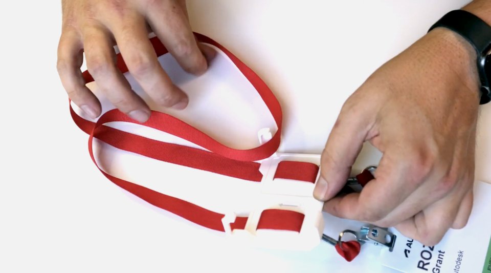
PREPARE THE LANYARD ASSEMBLY
- Hold the Lanyard Clip in front of you with the corner prongs pointed upward and the up arrow pointed away from you.
- Take your name tag with the front face up and lay the ribbon over the Lanyard Clip.
- Take the left side of the ribbon and tuck it into the tabs on the left side of the clip.
- Repeat with the right side of the ribbon on the right side of the clip.
- Allow the name tag to hang a few inches below the clip, you can adjust this later. Set the lanyard assembly aside.
Step 2
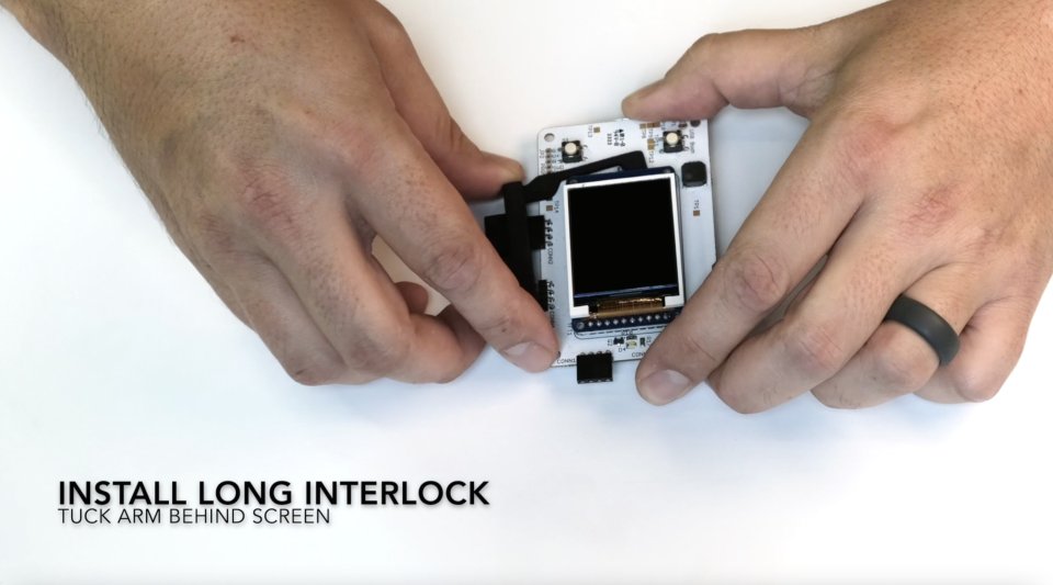
INSTALL THE LONG INTERLOCK COVER ONTO THE CIRCUIT BOARD
- Place the circuit board in front of you with the screen face up and the interlocking pins on the long side of the board pointed away from you.
- Locate the interlock bracket and orient it so that the serial numbers are face up and the long arm is on the right side pointed toward you.
This component is made of a flexible filament which allows the part to bend during the assembly process. - Slide the bracket onto the top of the circuit board edge so the pins slot into the openings.
- Gently bend the arm to the right slightly so tucks behind the right side of the screen. There are two raised dots on the extended arm, these face up and fit into the holes next to the screen.
- Press the edge of the bracket onto the top edge of the circuit board until seated.
Step 3
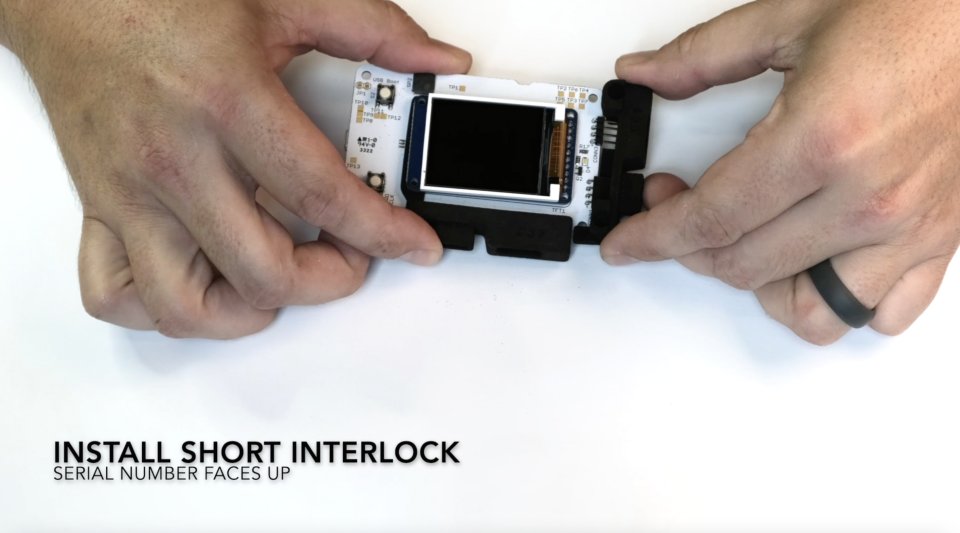
INSTALL THE SHORT INTERLOCK COVER ONTO THE CIRCUIT BOARD
- Locate the short Interlock Cover. Hold it so that the serial numbers point up and the holes are on the right side.
- Slide the short edge of the circuit board with connector prongs into the groove of the Interlock Cover.
- Align the screw holes on the cover with the holes on the corner of the circuit board. Press firmly until seated.
- Set the circuit board assembly aside.
Step 4
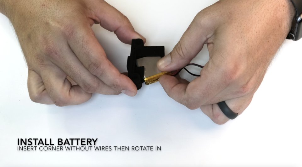
PREPARE THE BATTERY ASSEMBLY
- Identify the battery housing fixture. Hold it with the side with the two counterbores face up and the long rectangular extrusion pointed to the right. It should look kind of like an "F" shape.
- Next take the battery with the cable pointed toward you, then insert the right top corner into the rectangular extrusion of the housing fixture. Slightly rotate the battery clockwise so that the top left and bottom left corners fit snugly into the housing groove.
Step 5
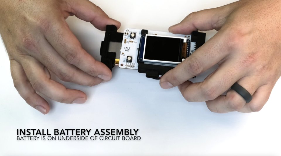
INSTALL THE BATTERY ASSEMBLY ONTO THE CIRCUIT BOARD
- Locate the circuit board and hold it with the screen face up. Rotate it so that the connection pins are on the left and top edges.
- Flip the battery assembly over so the battery is face down and the cable is pointed away from you.
- Slide the right side of the circuit board into the groove beneath the counterbores. Press firmly until seated. Ensure that the holes on the corner of the circuit board line up with the holes on the battery housing.
Step 6
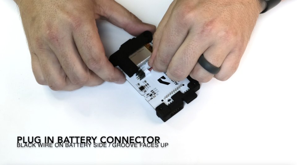
PLUG THE BATTERY INTO THE CIRCUIT BOARD
- Hold the circuit board with the screen face down and the battery side up.
- Plug the battery cable into the terminal that is located on the back face of the circuit board right next to the battery.
- Once connected to the battery power source, the device will turn on.
- Fold the battery cable and tuck it behind the battery, or fold it so it lays flat over the open space next to the battery. It will be held in place with the exterior casing later on.
- Set this assembly aside.
Step 7
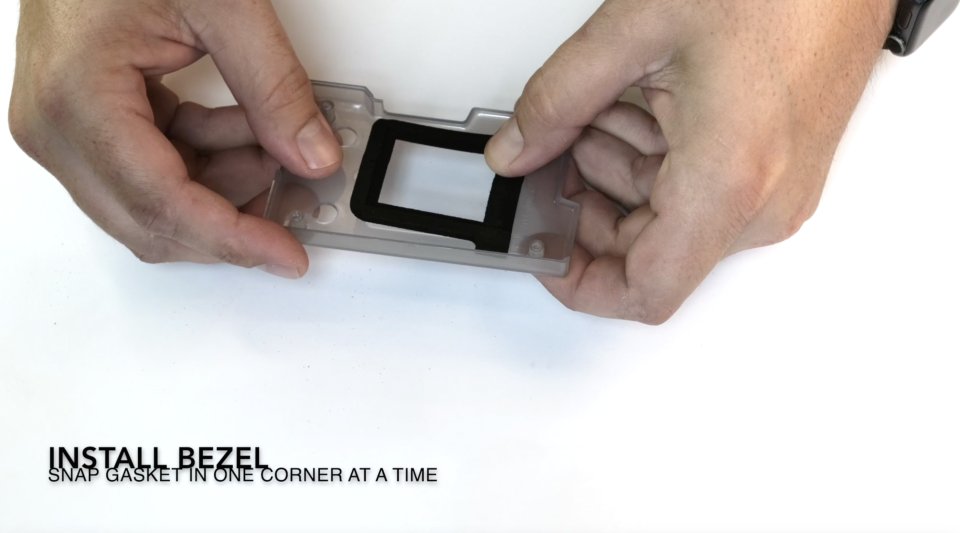
INSTALL THE BEZEL ONTO THE TOP ENCLOSURE PANEL
- Locate the Top Enclosure Panel, this is the one with the rectangular hole for the screen in the middle. Locate the Bezel, this is the rectangular rubber gasket.
- Hold the Top Enclosure Panel with the inside face up. Orient the Bezel over the hole for the screen so the tab on one corner points toward the long straight side of the Top Enclosure Panel.
- Press the Bezel into the rectangular hole so the gasket fits around the edge. Note: The tab on the Bezel should lay flat. If it does not lay flat, check the orientation and rotate the Bezel 180 degrees.
Step 8
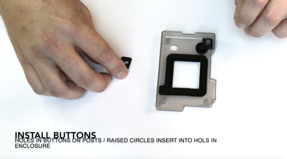
INSTALL THE BUTTONS ONTO THE TOP ENCLOSURE PANEL
- Locate the Right and Left Buttons. Set the Top Enclosure Panel on the table with the inside face up in front of you.
- Orient the Buttons so the small raised circle points face down. Set the Button into the corner so that the pegs slot into the hole on the square tab. The small raised circle will align with the hole on the panel. Note: There is a Right Button and a Left Button, rotate the button so that the square tabs seat into the corners of the Top Enclosure Panel.
- Press the Buttons into the panel so that they fit into the holes.
Step 9
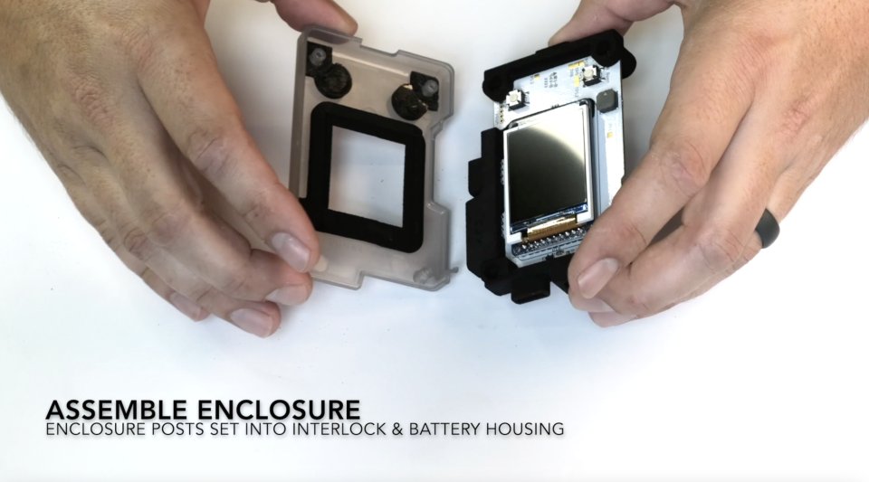
ASSEMBLE THE ENCLOSURE
- Set the circuit board assembly in front of you with the screen side facing up. Orient and place the Top Enclosure Panel over the circuit board so that the components line up.
- Flip this assembly over and place the Back Enclosure Panel so that it lines up with the Top Enclosure Panel. Ensure the battery cable is held out of the way and is either tucked behind the battery or held flat in the open space next to the battery.
- Align the seams so the Top and Back Enclosure Panels snap together. Note: There will be a small gap between the Top and Back Enclosure seams.
- Place the screws into the holes on the Back Enclosure Panel and screw them together. There will be some resistance, and thread until fully seated.
Step 10
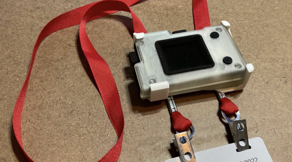
INSTALL THE LANYARD CLIP
- Lay the Lanyard Clip assembly in front of you with the corner clips face up. Allow the badge to hang a few inches below the bottom of the clip, you can adjust this later.
- Orient the device assembly so the screen is face up and the buttons are on the right side. Snap into place.
- Pull up on the lanyard gently until the metal crimps are touching the lanyard clip.
