& Construction

Integrated BIM tools, including Revit, AutoCAD, and Civil 3D
& Manufacturing

Professional CAD/CAM tools built on Inventor and AutoCAD
Parametric modelling is a computer-aided design (CAD) tool used for creating and manipulating parametric models. Parametric modelling allows designers and engineers to create intelligent models and then modify the entire shape of their design at once, not individual dimensions at one time. It eliminates the need to constantly redraw a design change every time a design dimension changes.
Parametric modelling is an approach to 3D CAD where you reach the design intent by including intelligence into your design to automate repetitive changes.
The basic principles of parametric modelling include:
Easily explore and evaluate various design alternatives by adjusting parameters. Experiment with different configurations, sizes and proportions for more innovative and optimised designs.
By associating parameters with performance indicators, easily assess and optimise how designs will perform based on specific criteria such as stability or energy efficiency.
Automate repetitive tasks to reduce the time and effort needed to make design changes. Automation saves time and reduces the likelihood of errors, resulting in cost savings during the design process.
Changes made to a parameter automatically apply to the model to maintain design consistency. This helps prevent errors that could arise from manually modifying multiple components of a design.
Parametric modelling software is used in the design and development of industrial machinery and equipment. It helps to create detailed 3D models of machines, optimise designs for efficiency and functionality, simulate machine operations and generate manufacturing-ready designs.
Parametric modelling software is utilised in the consumer products industry (US Site) for the design and development of a wide range of products. These include appliances, electronics, furniture and consumer goods. Designers and engineers can create visually appealing and functional product designs, simulate product behaviour and optimise designs for manufacturing and assembly.
Parametric modelling plays a critical role in the automotive and aerospace industries. It is used to design vehicles, aircraft and their components. Parametric modelling facilitates the creation of complex surface models, assembly structures and engineering documentation. It also supports the analysis and simulation of aerodynamics, structural integrity and performance.
Parametric modelling software is used in the medical and healthcare industries for the design of medical devices, prosthetics, implants and healthcare equipment. It assists in creating precise and customised models, simulating device performance and generating manufacture-ready products.
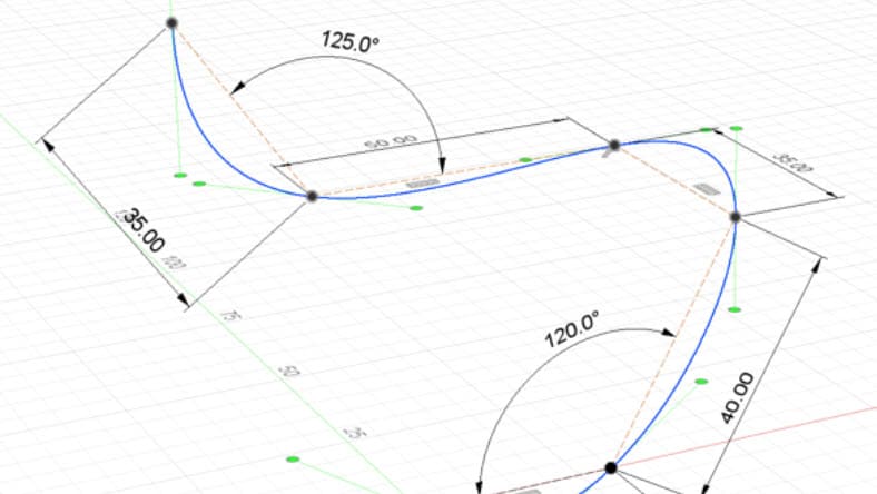
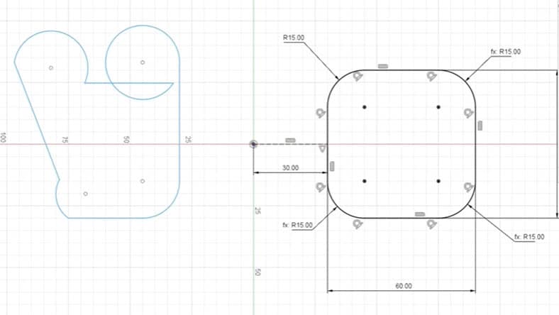
Sketching is the first step to creating a parametric model. Define the shape of and dimensions of your design by drawing 2D sketches on a plane.
Once a sketch is created, apply constraints to define the relationship between the various sketch elements. Constraints help designs remain consistent and allow for easy modifications.
Define parameters to control dimensions, sizes and other characteristics of the model. Dynamic changes to the model can be made by modifying the parameter values.
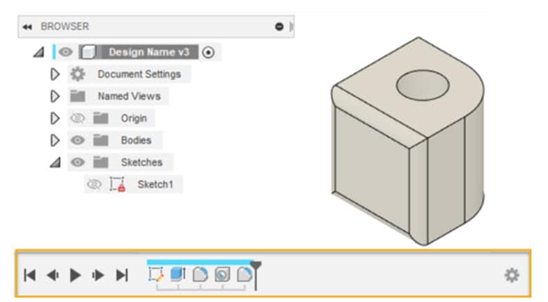
As features are added or modified, users can revisit previous design stages, modify parameters or easily adjust the model using the parametric timeline.
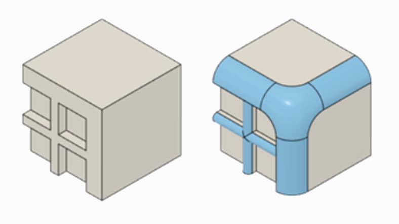
The foundation of parametric modelling takes a feature-based approach. Modifications applied to sketches such as extrusions, fillets or chamfers are applied to create a 3D model.
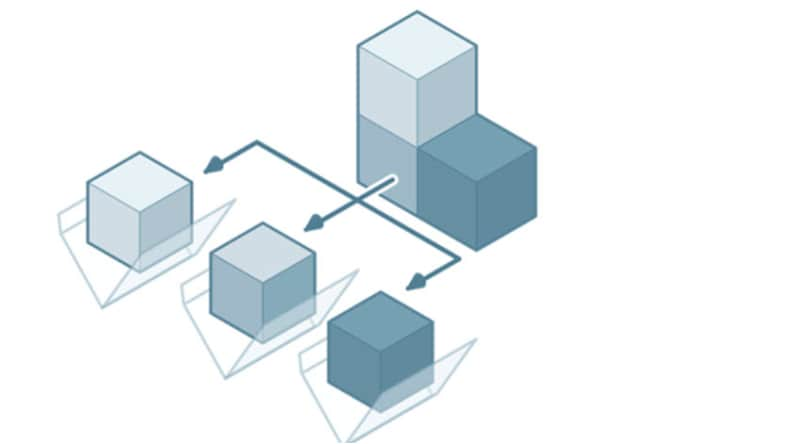
Multiple components are combined to form the complete product. Define relationships between components, simulation motion and visualise the assembled model.
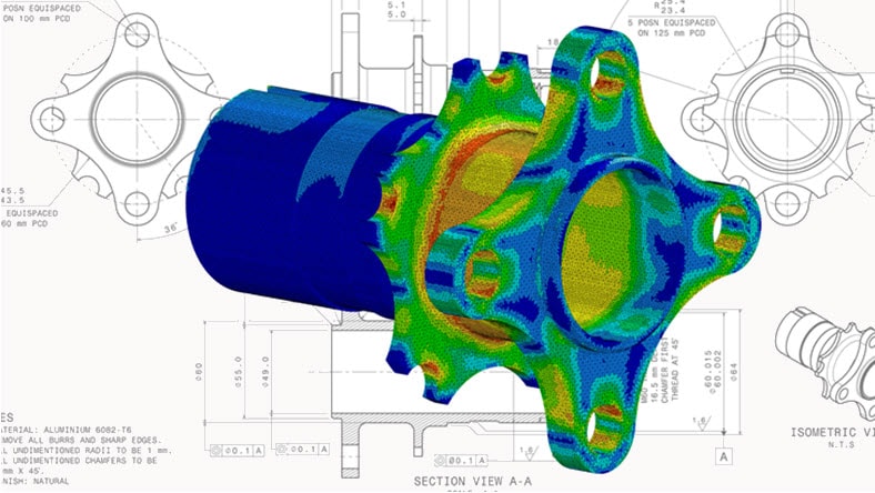
Assess product performance and structural integrity of designs to identify potential issues, make design optimisations and make sure compliance requirements are met.
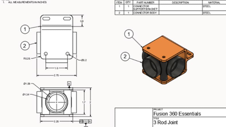
Create detailed drawings, including dimensions, annotations and views. Generate 2D drawings with precise control over scale, projection types and detailing standards.
Sheet metal capabilities in Autodesk Fusion allow engineers and designers to create precise models of sheet metal components. Users can define parameters such as material thickness, bend allowances, hole sizes and other geometric features relevant to sheet metal fabrication.
The Autodesk Fusion electronics workspace includes a variety of tools that include editors for schematic capture, PCB layout, library management, 3D PCB editor, manufacturing data generator, mechanical CAD capabilities and more.
Autodesk Inventor Tube & Pipe adds design tools for routing rigid pipes, bent tubes and flexible hoses to mechanical assemblies or product designs in the assembly environment.
The Frame generator in Autodesk Inventor creates internal frame and external frame assemblies for machines from the assembly and weldment environments.
Powerful product design and engineering tools for 3D mechanical design, simulation, visualisation and documentation.
This step-by-step tutorial will introduce you to parametric modelling. Learn how to use a canvas image, project edges into a sketch, create a sketch plane and apply appearances and physical materials.
Learn how to use sketching, solid modelling and parametric modelling in Autodesk Fusion to create and modify models for additive manufacturing.
Learn about the advantages of parametric modelling in Autodesk Fusion with this short overview.
Regardless of your workflow preferences, your tools should be flexible enough to accommodate your preferred processes. Learn the difference between parametric modelling and direct modelling, including when and how to use each in Autodesk Fusion.
Take a deeper look at the term parametric design process and see what it means for today's architects and the future of architectural design.
See how the modern furniture design process allows designers to utilise woodworking 3D design software and parametric design features.
Parametric modelling involves using mathematical parameters or functions to define the relationships between data points. It assumes a specific functional form for the data distribution or relationship. Non-parametric modelling does not assume a specific functional form for the data distribution or relationship. It allows for more flexibility in capturing complex patterns and does not rely on predefined assumptions.
Parametric modelling is a feature-based approach where 3D models are created and modified by defining parameters, constraints and relationships between geometric elements. Direct modelling is an approach where 3D models are created and modified without relying on parameters, constraints or a history tree. It focuses on manipulating the geometry directly.
CAD (Computer-Aided Design) refers to the use of computer software to create, modify and analyse 2D or 3D digital models. Parametric modelling is a specific approach or methodology used within CAD software for creating and modifying models.
Parametric modelling itself does not inherently include simulation capabilities. However, parametric modelling software often integrates with simulation tools (US Site) or offers simulation modules that can be used to analyse and simulate real-world conditions. These simulation capabilities allow designers and engineers to evaluate the performance, behaviour and response of their parametric models under various conditions.
Parametric models capture design intent by defining parameters, constraints and relationships between different model elements. When a design change is made, the software automatically updates the model while maintaining the intended relationships. This helps preserve the overall design intent.
