00:02
We will identify the project location and how this can inform the initial stages of a project.
00:12
Before we get started, let's walk through the API.
00:17
So, we have Files where we can save projects, editing abilities, and we have viewing potential with different angles of the project.
00:26
We also have Linework and Locations, settings for how the interface works, generate insights and collaboration.
00:47
On the far right, we have quick user tools to interrogate the model.
00:54
So, we're going to click on the Location.
00:56
We're going to activate the coordinates of this project.
01:01
And we're going to search for this satellite image.
01:10
So, we can zoom into the location.
01:14
We can flick between the different options Aerial View, Ordnance Survey.
01:24
In this instance, we're going to import that location.
01:29
But we also have the ability to import a satellite image.
01:33
And we're just going to zoom into that location.
01:36
We're going to go to the Aerial View.
01:39
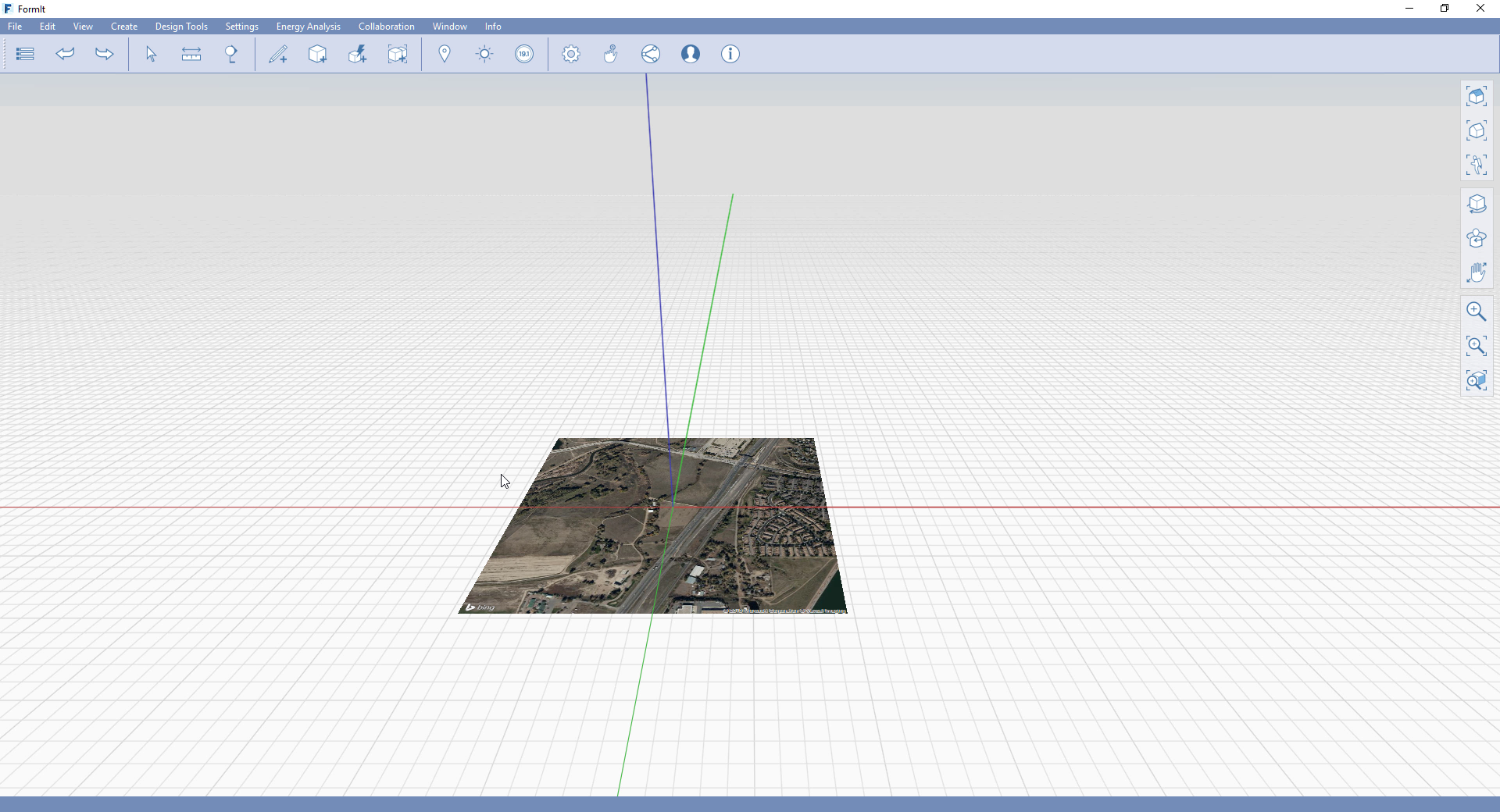
We're going to import satellite.
01:41
We're going to zoom out so that we can see the full extent of the site.
01:59
We're able to navigate within a 3D View the actual image of the site.
02:06
This is really useful.
02:08
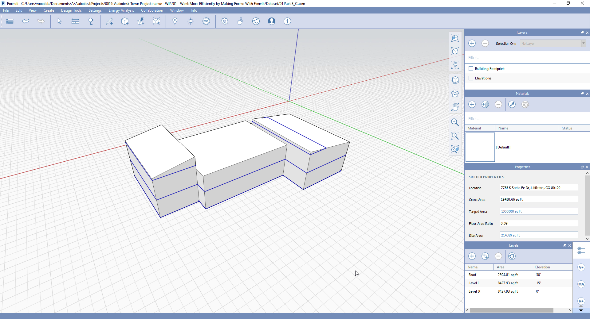
So, what we now have is the environment set up for the location of the project.
02:18
These lines identify the different axes...
02:24
For the X and Y directions of a 3D environment.