00:02
We're going to establish the Levels to a project,
00:06
and how we can identify early-stage project information to enable the design process.
00:16
Before we start setting up the Levels, we're going to activate the dialogue boxes that we need for this particular stage of the project.
00:26
So, we're going to identify the Levels, Layers and Properties. And these are displayed on the far right of the screen.
00:36
These can be adjusted by pulling them up and down or pulling them away from the docking station.
00:43
We can click on the "+" sign to create a Level within the project.
00:50
This could be done multiple times.
00:52
If, however, you have multiple levels reoccurring, you can set the distance for each Level.
00:59
In this instance, we're just going to create three levels for this particular project.
01:08
The elevation distance for the Level can be changed as and when required.
01:15
We can also rename each the Levels to represent a particular Level to the building that you might be designing.
01:35
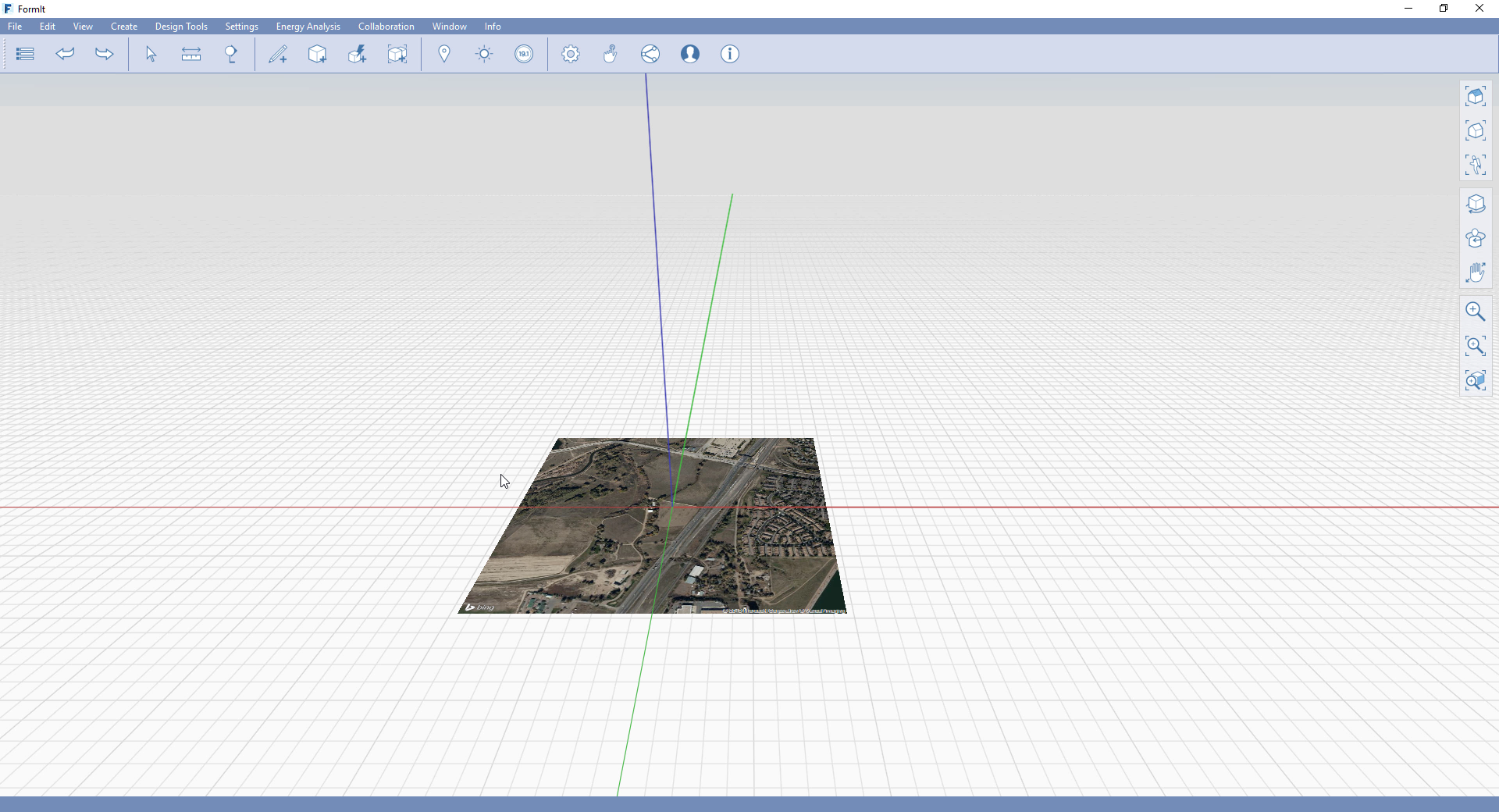
Once we have completed that, we're going to focus on the area of the site.
01:40
So, you can do that by selecting the Draw Creation tools,
01:45
to sketch out an initial boundary of your site location.
01:51
So, this is where the building plot will be positioned.
01:54
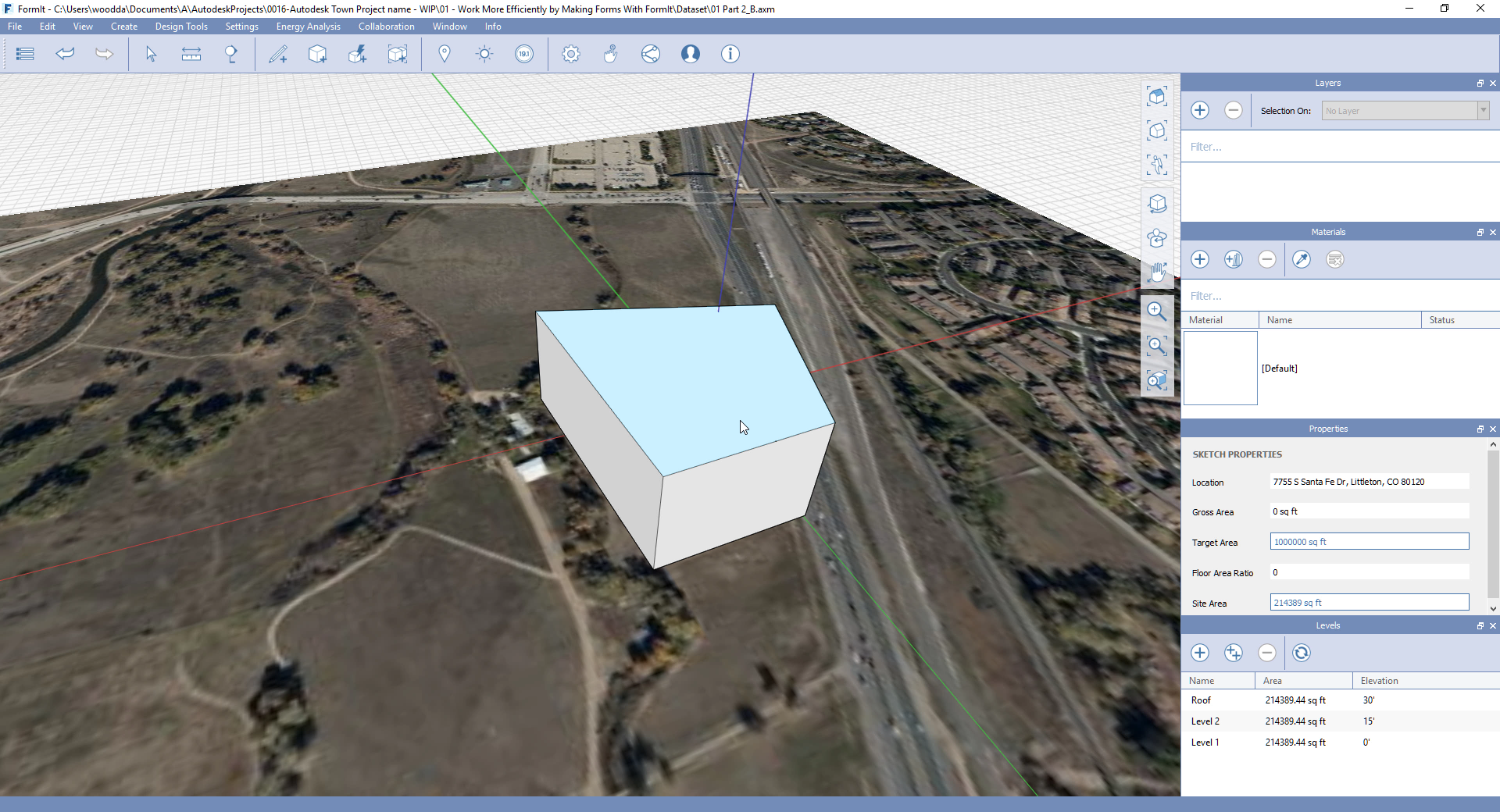
By selecting the surface, we can identify the area of this building plot.
02:01
So, this is really useful to establish within the context of the site area,
02:07
but also the target area and the gross area.
02:11
So, depending on what you require in terms of early stage interaction with the project information,
02:20
this can now enable designers to quantify the scope of the project.
02:32
By selecting the surface, you can Push/Pull this object to identify the volume,
02:39
and also attach a name to this particular object.