Lesson: Creating sketches using included parameters
In this lesson, we will develop a Pier component for InfraWorks using a file that has parameters preloaded.
Learning Objectives:
• Create a UCS controlled by parameter
• Develop a sketches using parameters
• Build 3D features from sketches
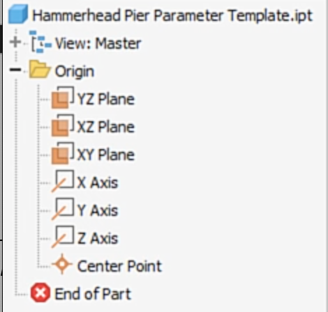
1. Open Hammerhead Pier Parameter Template.ipt file.
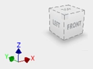
2. Orient the ViewCube So that the X Axis is to the right and the Z Axis is pointing up.
3. Set the ViewCube face to Front.
4. Set a Home View orientation looking at the top, left and front faces as well.
5. Expand the Origin folder in the browser and turn on the visibility of the planes, axes, and center point.
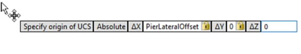
6. Start the UCS tool.
7. Set the X value to PierLateralOffset, the Y and X values to 0.
8. Turn on the Construction line option from the Format tab.
9. Draw a ~20in horizontal line above the model center point.
10. Draw another line from the model center point to the midpoint of the horizontal line.
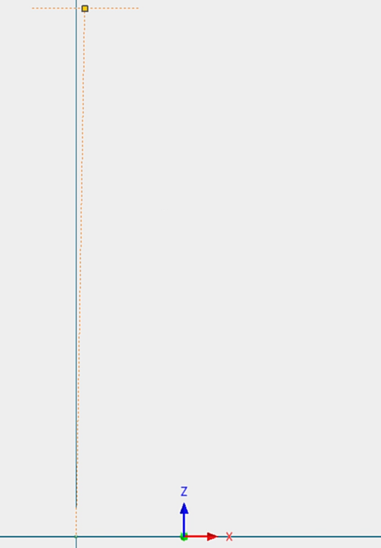
11. Project the centerpoint of the UCS
12. Draw a vertical line from the centerpoint of the UCS toward the horizontal line.
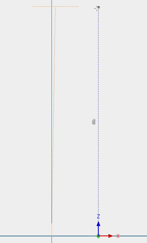
13. Apply a Vertical constraint to the line drawn from the model centerpoint.
14. Add a dimension from the centerpoint to the horizontal line and use the List Parameter option to pick the PierHeightPlustVerticalAdjustment parameter.
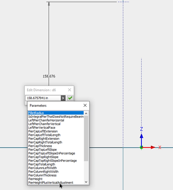
15. Adjust the size and position of construction lines to fit the update scale of the model.
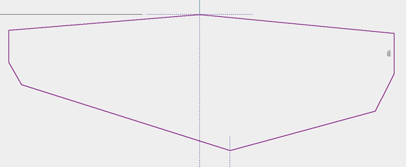
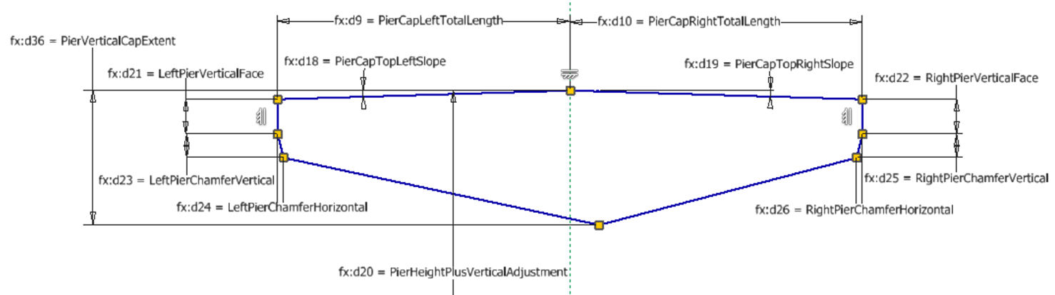
16. Sketch the profile of the Cap making the lines on the sides Vertical.
17. The top of the profile should be connected to the middle of the horizontal construction line.
18. Connect the bottom point to the line drawn from the UCS.
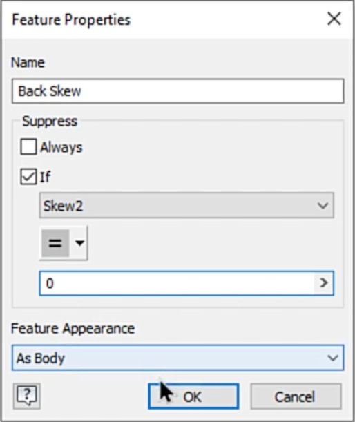
19. Right-click on the Back Skew feature and select Properties.
20. Create a Suppression rule that suppresses the feature if the value of the Skew2 parameter is equal to 0.
21. Use the List Parameters option or type the parameter names listed below to constrain the geometry.
22. Finish the Sketch and rename it in the browser to Cap Sketch.
23. Start the Extrude tool.
24. Extrude the profile symmetrically setting the Distance A value to PierCapThickness.
25. Begin a new sketch on the XZ plane of the part origin.
26. Project the centerpoint of the UCS into the sketch.
27. Add a horizontal line from the origin to the left a distance of PierColumnLeftWidth.
28. Add a horizontal line from the origin to the right a distance of PierColumnRightWidth.
29. Project the bottom edges of the Cap into the sketch.
30. Draw vertical lines from the endpoints of the column to the projected bottom of the Cap.
31. Add lines to cap the top of the column sketch.
32. Finish the sketch.v
33. Rename the sketch Column Sketch.
34. Start the Extrude tool and create a symmetrical body setting the Distance A value to PierColumnThickness.
35. Place a fillet with a Radius of FiletRadius on each side of the Column where the Column meets the Cap.


