00:03
Hello, my name is Thom Tremblay.
00:06
In this course, we'll be taking a look at an overall bridge design workflow.
00:11
And in these lessons,
00:12
we'll be focusing on how Autodesk Inventor can be used to create custom components to be used in InfraWorks for your bridge designs.
00:22
In this lesson, we'll be creating another girder component, but we'll be doing it in a fashion where it can be imported as a generic component.
00:30
Most importantly, we'll be focused on the use of suppression of features to enable higher functionality when it comes to face drafts.
00:38
Opening the Generic Component Sketches.ipt file,
00:42
you'll find two sketches that have the same geometry but use parameters that are unique to each sketch to specify the profiles.
00:51
The sketches for these profiles, rather than being based on planes that are native to the part, are based on UCS’s that were created in the component.
01:01
A back UCS and a front UCS.
01:05
If we take the end-of-part marker and roll it back over the sketches so all we see are the UCS and open the parameters dialog box,
01:13
we can modify the equation in the segment length parameter to see how these UCS's are related to one another.
01:23
Turning the sketches back on, we can see now they're closer together.
01:29
To create the 3D model, we'll use the loft tool to loft first the outside profiles of both sketches.
01:39
Then turning the sketches back on, create another loft to cut the inside profile between the two sketches out of the model.
01:50
This will give us our complete model.
01:52
And just to test it, we can restore the 8-meter segment length parameter value.
01:59
After updating the model, we can see everything works great.
02:04
It is possible to modify the angle of either face by editing the UCS.
02:11
However, that skews the geometry of the component itself.
02:15
So that's not an acceptable approach in this case.
02:20
In order to build flexibility into the component to allow the ends to change angle,
02:25
both about the y-axis and about the x-axis, we'll add face draft features.
02:32
Expanding the UCS objects in the browser, we'll be able to access their planes and axes.
02:38
We'll start the draft tool from the panel and use the fixed plane option, which is the middle option on the left.
02:46
This will allow us to select a plane as the fixed plane and have other faces change their angle based on that plane.
02:56
We'll select the front yz-plane as the first plane.
03:01
And then select the front face.
03:04
The draft angle that was in the dialog box will automatically be applied.
03:09
We can change this to five to see the effect.
03:13
Or to minus 10 to see how the angle of that face is affected by this draft.
03:21
We can also enter a parameter.
03:24
We'll create skew 1 equals 3 as the value.
03:34
Next, still using the fixed plane, use the yz-plane of the back UCS as the fixed plane and select the back face.
03:45
For the draft angle, we'll use skew 2 with a value of 5.
03:53
This will create the features in the browser.
03:58
If we look at the top view, we can see how our girder section is now kind of a rhombus.
04:04
So, let's open up the parameters and make sure everything's working as we expect.
04:10
Scrolling down to the bottom of the model parameters, because those parameters were created in line, we can change the values to check them.
04:19
If I set the value to 0 and select "Update", Inventor will give us an error message.
04:25
You cannot have a draft angle of 0, which creates a problem because there are going to be many times where we do want those ends square.
04:36
So, I'll set it back to three, make sure it still works and then we'll close the dialogue.
04:42
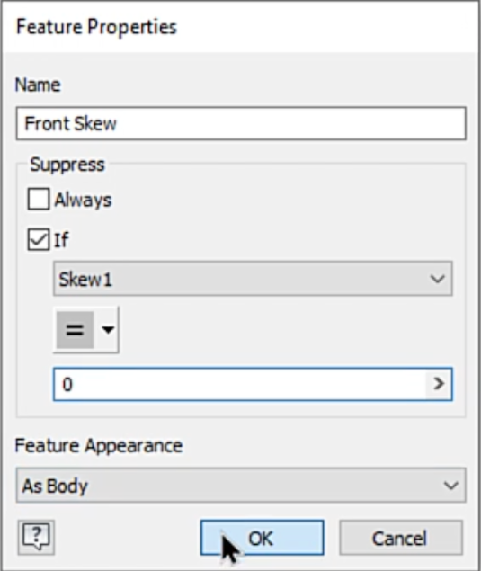
After quickly renaming the draft angel, I'll right click on the front skew feature and select "Properties".
04:52
In the Properties, I'm going to create a condition that says if the value of UCS 1 is equal to 0, suppress that feature.
05:04
And we'll repeat this for the back skew feature as well.
05:09
Now going into the parameters, finding those skew values, and changing them both to 0.
05:15
When I update, we see that the ends of our girder come parallel and perpendicular to the edges.
05:23
So, this works perfectly.
05:26
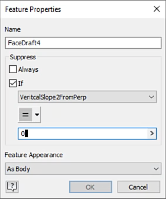
Now we'll repeat the process, creating fixed-face drafts based on the xz-planes of the front and back.
05:37
For these features, we'll use a parameter that was already in the file called vertical slope 1 from purp and vertical slope 2 from purp.
05:45
One being in the front.
05:49
Then we'll add the same rule about suppressing if the value is 0 to those parameters.
05:59
Now let's take a look at the right side.
06:03
Open up the parameters dialog box and test it with a value of 0.
06:09
Everything is working well.
06:17
So, we'll proceed to exporting our model.
06:21
Going to the environments tab, we'll select the "Infrastructure Part Shape Utilities" and use the export template tool.
06:32
We'll set a path for the export of our model and give it a name.
06:37
Selecting "Export" when we're done.
06:41
Then we can close the dialogue.
06:43
You'll notice that the model that we were working from has been replaced by the exported component.
06:49
And then we can select "Finish Infrastructure" to return back to the modeling environment.