00:08
Now that we have learned how to put together
00:10
our schematic wiring drawings along
00:13
with all the schematic components,
00:14
we can actually starter run reports.
00:17
So in this case, we're going to look
00:19
at just the schematic reports.
00:21
We will look at the full bill of material
00:23
and the rest of the panel reports
00:25
when we get into that section.
00:27
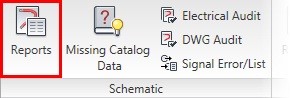
If I move over to the reports tab of the ribbon,
00:31
you'll see that there is a section for schematic reports
00:33
as well as the panel reports.
00:36
I'm going to click on the schematic reports button here.
00:39
In the schematic reports dialog box,
00:41
you will see a list of the different reporting tools
00:44
that we have within this field.
00:47
These are all customizable.
00:49
So do not panic if you don't see the type of report
00:52
You can absolutely adjust these and make them
00:54
their own very, very easily.
00:57
The key is getting to the report that's closest to what you need
01:00
and then tweaking it from there.
01:03
So the most important one, the one
01:04
that everybody wants to talk about the most
01:06
is the bill of material.
01:08
Now, we will talk about bill of material
01:10
again in a later lesson, because there's
01:13
a bigger bill of material that is your full project's bond
01:16
that is done out of the panel reports.
01:19
Because those include items in the panels
01:21
that are not currently in the schematics.
01:23
Things like enclosures, DIN rails, and so on.
01:26
But in this one, if you wanted to run a bill of material
01:29
to take a look at the whole project or even just
01:31
your active drawing, if you want to put a bill of material
01:34
on just that, you can run those filters.
01:37
You can also run it against specific categories
01:40
like, your schematics, one line, one line bus tap, hydraulic,
01:44
pneumatic, and PNID.
01:46
We don't spend a lot of time on that
01:47
in this particular training session,
01:49
but please note that there is a full symbol
01:52
library within electrical for hydraulic, pneumatic, and PNID
01:57
All of those types of drawings can
01:59
be integrated into your AutoCAD electrical projects
02:02
and reported on as well.
02:04
From here, if we had inventor parts, which
02:07
is part of our EMS workflow or electromechanical workflow,
02:11
you could also include any inventor parts
02:14
that are not associated here.
02:16
And then you also choose whether or not
02:17
you want to have cables, connectors,
02:19
and jumpers included.
02:20
There are many different display options.
02:22
You can take a look at how they're all put together.
02:24
The most common is the normally tallied format.
02:27
And then you can choose to extract to do bill of materials
02:30
by certain installation or location codes.
02:33
If you remember from the earlier lesson on installation
02:36
and location codes, those are specific fields
02:39
that we can filter many different report types by.
02:42
So I could come in and actually look at a name location
02:45
and find a specific location code I wanted
02:48
to run a bill of material on.
02:50
In this case, though, for demonstration purposes,
02:53
I'm going to put them to all so we can see everything.
02:57
I'm going to click OK.
02:58
And then I'm going to say I want all drawings to be scanned.
03:01
It will only pull my schematic drawings for me.
03:05
It will not look at any symbols that are not schematic.
03:08
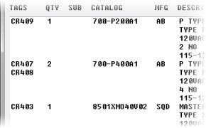
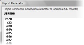
And then it pulls all that data together
03:10
into this report generator.
03:12
Now this generator may look a bit streamlined here
03:16
in the categories, but we have lots of different formatting
03:18
options that you can then put it into.
03:21
You can put it on a drawing as a table, which
03:24
we will do in a second, or you can save it to a file.
03:27
Every single report type that we have in AutoCAD electrical
03:31
has the ability to go to an ASCII, Excel, Microsoft Access
03:35
database, XML, or CSV file.
03:39
If you choose to do that, you will still
03:41
be taken back into this dialog box to then
03:43
put it on the drawing as well.
03:45
So you have options to do both.
03:47
It's not one or the other.
03:48
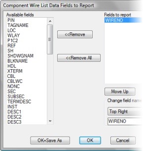
The most important thing to talk about in here
03:50
is changing the report format.
03:52
If you need to change anything, this is where you do it.
03:55
The list of available fields is on the left hand side
03:58
and every report is different on what
04:00
those available fields are.
04:02
From there, you choose which fields you actually
04:05
want it to extract on.
04:07
And then you can even change what the titles of these fields
04:10
For instance, if I didn't want it to say tags anymore,
04:13
but I wanted it to say ID, I could have it do that.
04:19
And you'll see updates as soon as you bring it over.
04:22
Sometimes, there are super fields
04:24
like this description one here that concatenate
04:27
multiple fields together.
04:28
So description is actually bringing
04:30
in all of these individual fields into one big grouping.
04:35
If any one of those fields is pulled out
04:37
to be its own category, it will not
04:39
be reported on when it's extracted.
04:41
In this section, it will get its own category.
04:45
So for instance, manufacture and catalog
04:48
number are in this big group, but they are also
04:50
their own categories here.
04:52
So they will not be moved into this description field.
04:54
It's a catch all to be able to grab as much information
04:57
as you want to pull into that particular report.
05:01
If there was something I wanted, for instance, one of my user
05:04
fields, which perhaps I'm using to put my own custom part
05:08
number on, then I could have it bring that in.
05:11
And I probably would change that to my company name,
05:18
And it will remember all of your report formats for use later.
05:22
You can also save these different report formats
05:27
That's what this save as is.
05:29
So you can save that dot set file
05:32
to be able to help you use and reuse that with other reports
05:35
that you want to be able to bring
05:37
that same information into.
05:40
There is also in edit mode that if needed,
05:42
you could add in additional part numbers,
05:45
in as case, or other fields depending
05:47
on what type of report is that you're
05:49
doing to be able to edit those line items if it's not
05:53
data that's currently in the drawings.
05:55
My advice though, is to make sure
05:57
that that information is always built into your drawing
05:59
set so that you don't have a mismatch between your reports
06:03
and the drawings themselves.
06:04
If you needed to rerun this, and once again,
06:07
it extracted everything from your drawings,
06:09
that you would have to keep doing that manual edit.
06:12
Better off, just putting it directly into the components
06:16
Once we have it set up how we want it,
06:18
we can choose to print this.
06:20
Obviously, save it to that file format I just showed
06:23
or then put it on a drawing.
06:25
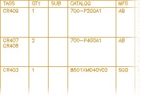
When you click put on drawing, you automatically
06:27
go into a table generation setup dialog box.
06:32
This utilizes AutoCAD electricals tables, which are
06:36
very much like Excel tables.
06:38
And you have different options to choose
06:40
from when you're inside before you actually place it.
06:43
If you just place it right now, it
06:45
will set up with all automatic settings.
06:47
However, you can tweak those and adjust them
06:50
to whatever your needs are.
06:52
If you were to choose this insert new non-updatable,
06:55
that would be a report that will not
06:58
update if you wanted to rerun this report again to get
07:01
refreshed information on it.
07:03
It would just stay static on your drawing.
07:06
The update existing would be highlighted
07:08
if this report existed already on the drawing
07:11
and you just wanted it to refresh it
07:13
as opposed to inserting it new.
07:16
You can also have this split across multiple sections
07:19
and multiple drawings.
07:21
The way to do that is to define your section placement here,
07:24
define how many rows are in each section,
07:27
and then you can tell it how many sections
07:30
you want on a drawing.
07:31
If it starts getting very large, it will then split itself
07:34
across multiple drawings.
07:36
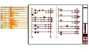
Once you're done, you click OK and then
07:38
you can put this report, I'm going to put it off to the side
07:41
because I don't have enough room inside of my window here,
07:46
Like I said, it takes you right back in.
07:47
I could save it to a file now.
07:49
In this case, I will close it.
07:51
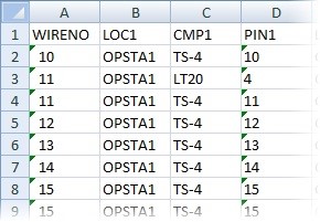
And there is my report.
07:53
Again, this is how it would look if it went into Excel.
07:55
And obviously you have lots of other options
07:57
with the other four categories of files.
08:00
One last thing to highlight in reports
08:03
is just looking at some of the other types of reports you
08:05
can extract from schematics.
08:08
You can extract wire from two, you
08:10
can extract many different kinds of PLC reports,
08:14
terminals, connectors, cable from twos,
08:17
and even wire labels.
08:19
And depending on the extraction that you use
08:22
and the Export to say, Excel or something else,
08:25
you can often bring that into label makers and other tools
08:30
to be able to have those go right into the machines
08:32
that you're having build the labels, nameplates,
08:35
when we look at nameplates, and any other things that you
08:37
need it to be brought into.
08:39
The same thing goes for the bill of materials.
08:41
Most people are using an ERP system
08:44
that will accept any one of those five file formats for you
08:48
to be able to bring that directly
08:50
into your ERP for purchasing so that you do not
08:52
have to duplicate this information when you
08:54
go to create a purchase list.
08:56
Please take a moment to do the exercise on schematic reports.