| |
| |
Completion Time: 40 Minutes
|
Completion Of Creating Panel Layouts Lesson
| |
Objective: In this exercise, you insert and edit footprint symbols on an operator station panel layout. You complete the following steps:
■ Extract a schematic component list from the current project.
■ Insert several components from the list in your panel drawing as footprints.
■ Add nameplates.
■ Edit the footprint and automatically update the nameplate and schematic components.
■ Surf to the schematic drawing to review changes.
|
| |
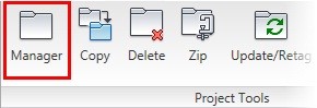
1: If the Project Manager is not displayed, on the Project tab, Project Tools panel, click Manager.
|
| |
2: If Panel_Layouts_NFPA is the active project, skip to step 6. If it is open but not active, in the Project Manager, do the following:
■ Right-click Panel_Layouts_NFPA.
■ Click Activate.
■ Skip to step 6.
|
| |
3: In the Project Manager, click Open Project.
|
| |
4: Browse to where you installed the exercise files and select Panel_Layouts_NFPA.wdp. Click Open.
|
| |
5: From the Projects list, click the expansion node next to Panel_Layouts_NFPA to expand the drawing list.
|
| |
6: Right-click Panel_Layouts_NFPA_08.dwg. Click Open.
|
| |
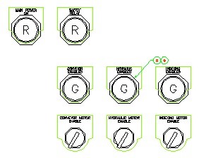
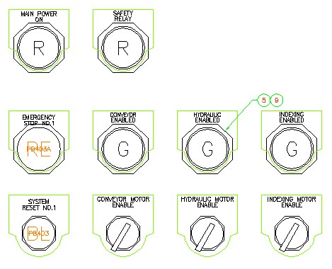
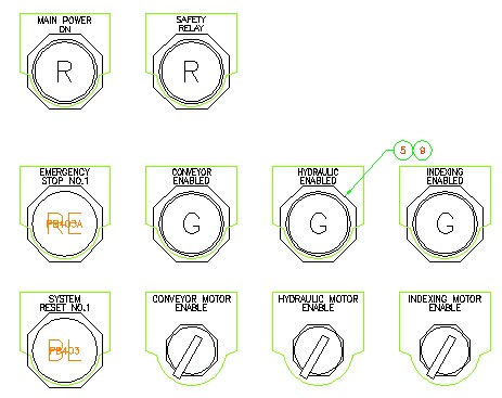
7: Zoom in to the left side of the operator station front layout.
|
| |
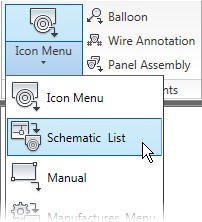
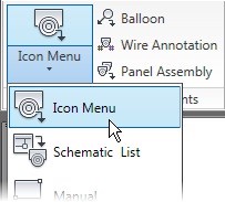
8: On the Panel tab, Insert Component Footprints panel, Icon Menu flyout, click Schematic List.
|
| |
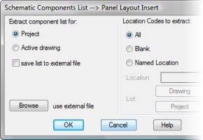
9: In the Schematic Components List dialog box, do the following:
■ Click Project.
■ Click All.
■ Click OK.
|
| |
10: In the Select Drawings to Process dialog box, click Do All. Click OK.
|
| |
11: Insert Components from a List:
In the Schematic Components dialog box, click Sort List.
|
| |
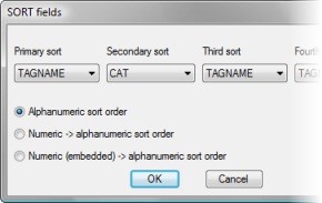
12: In the Sort Fields dialog box, from the Primary Sort list, select TAGNAME. Click OK.
|
| |
13: In the Schematic Components dialog box, click Mark Existing.
|
| |
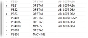
14: Scroll through the list to PB403 and PB403A.
|
| |
15: Select PB403 and PB403A. Press and hold Shift to select both entries.
|
| |
16: For Rotate, enter "0"
|
| |
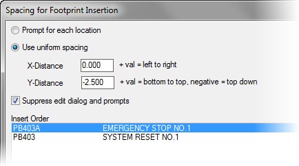
18: In the Spacing for Footprint Insertion dialog box, do the following:
■ Select Use Uniform Spacing.
■ For X-Distance, type "0.00"
■ For Y-Distance, type "-2.50"
■ Select the Suppress Edit Dialog and Prompts check box.
■ Change the insert order so that PB403A is first and PB403 is second.
■ Click OK.
|
| |
19: Select the insertion point for the first footprint below the Main Power On light and to the left of the Conveyor Enabled light. (Hint: Use Object Snap Tracking to line up exactly on the centers of the components.)
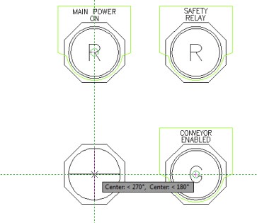
AutoCAD® Electrical inserts both switches, and you return to the Schematic Components dialog box to continue inserting footprints.
|
| |
20: In the Schematic Components dialog box, click Close.
|
| |
21: In the Update Other Drawings dialog box, click OK.
|
| |
22: If prompted, in the Qsave dialog box, click Always Qsave.
|
| |
23: Insert Nameplates:
On the Panel tab, Insert Components Footprints panel, Icon Menu flyout, click Icon Menu.
|
| |
24: In the Insert Footprint: Panel Layout Symbols dialog box, click Nameplates.

|
| |
25: In the Panel: Nameplates dialog box, click Nameplate, Catalog Lookup.

|
| |
26: In the Nameplate dialog box, click Catalog Lookup.
|
| |
27: In the Catalog Browser dialog box, do the following:
■ In the Search field, type 800T*
■ In the Catalog column, select 800T-X59E.
■ Click OK.
|
| |
28: In the Nameplate dialog box, click OK.
|
| |
29: Select both switches that you inserted earlier, PB403 and PB403A. Press ENTER.
|
| |
30: In the Panel Layout - Nameplate Insert/Edit dialog box, click OK to accept the default information for PB403.
|
| |
31: In the Panel Layout - Nameplate Insert/Edit dialog box, click OK to accept the default information for PB403A.
|
| |
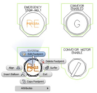
32: Edit Footprint and Update Links:
Right-click PB403, System Reset No.1. Click Edit Footprint.
(Be sure to select the switch footprint, not the nameplate.)
|
| |
33: In the Panel Layout - Component Insert/Edit dialog box, click Catalog Lookup.
|
| |
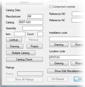
34: In the Catalog Browser dialog box, do the following:
■ In the Search field, type 800T*
■ In the Catalog column, select 800T-A2A.
■ Click OK.
|
| |
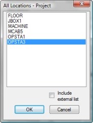
35: In the Panel Layout - Component Insert/Edit dialog box, in the Location section click Project.
|
| |
36: In the All Locations - Project dialog box, select OPSTA3. Click OK.
|
| |
37: In the Panel Layout - Component Insert/Edit dialog box, click OK.
|
| |
38: In the Panel Footprint Update? dialog box, click Yes, Change It.
|
| |
39: In the Update Related Components? dialog box, click Yes-Update.
|
| |
40: In the Update Other Drawings? dialog box, click OK.
|
| |
41: If requested, in the Qsave dialog box, click OK.
The existing footprint is changed to match the new part number. The current drawing is saved and closed. AutoCAD Electrical opens Panel_Layouts_NFPA_04.dwg and updates PB403 with the new information. AutoCAD Electrical saves and closes Panel_Layouts_NFPA_04.dwg, and then reopens Panel_Layouts_NFPA_08.dwg.
|
| |
42: On the Quick Access toolbar, click Surfer.

|
| |
43: In the drawing, select the PB403 push button footprint.
|
| |
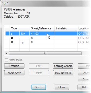
44: In the Surf dialog box, select the parent schematic reference for PB403. Click Go To.
|
| |
45: If requested, in the Qsave dialog box, click OK.
AutoCAD Electrical saves and closes Panel_Layout_NFPA_08.dwg. AutoCAD Electrical opens Panel_Layout_NFPA_04.dwg and zooms in to PB403.
|
| |
46: In the Surf dialog box, click Edit.
Notice how the information on the schematic symbol is updated with the edits from the panel drawing.
|
| |
47: In the Insert/Edit Component dialog box, click OK.
| |
|
|
|


