Prerequisites
Completion of the Using the Spreadsheet to PLC I/O Utility Lesson
Objective: In this project you use the default demoplc.xls spreadsheet and hard-coded default settings to generate three PLC drawings.
Process: Create PLC Drawings from a Spreadsheet
Instructions
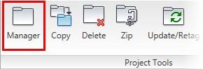
1: If the Project Manager is not displayed, on the Project tab, Project Tools panel, click Manager.
2: If PLC_Modules_NFPA is the active project, skip to step 6. If it is open but not active, in the Project Manager, do the following:
■ Right-click PLC_Modules_NFPA.
■ Click Activate.
■ Skip to step 6.
3: In the Project Manager, click Open Project.
4: Browse to where you installed the exercise files. Select PLC_Modules_NFPA.wdp. Click Open.
5: From the Projects list, click the expansion node next to PLC_Modules_NFPA to expand the drawing list.
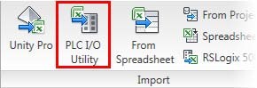
6: On the Import/Export Data tab, Import panel, click PLC I/O Utility.
7: In the Select PLC I/O Spreadsheet Output File dialog box, in the User directory, which opens by default, select demoplc.xls. Click Open.
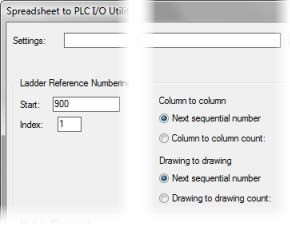
8: In the Spreadsheet to PLC I/O Utility dialog box, leave the Settings box blank. This enables you to use the hard-coded default settings that match the demoplc.xls file.
9: Under Ladder Reference Numbering, do the following:
■ For Start, type 900
■ For Index, type 1
■ Under Column to Column, click Next Sequential Number.
■ Under Drawing to Drawing, click Next Sequential Number.
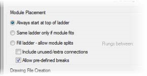
10: Under Module Placement, do the following:
■ Click Always Start at Top of Ladder.
■ Clear Include Unused/Extra Connections.
■ Select Allow Pre-Defined Breaks.
11: Under Drawing File Creation, do the following:
■ Clear Use Active Drawing.
■ For Starting File Name, type PLC_Module_NFPA_12
■ Click Free Run.
■ For Sheet, type 12
■ Select Add New Drawings to Active Project.
■ Click Start.
12: Look in the Project Manager and verify that the following three drawings have been generated and added to the project drawing list: PLC_Module_NFPA_12.dwg, PLC_Module_NFPA_13.dwg, and PLC_Module_NFPA_14.dwg.


