00:08
Now that we've actually learned
00:09
how to insert ladders, edit wires, and do point
00:13
to point wiring, let's talk about how to get
00:16
your numbers on our drawing.
00:19
It's one of the most tedious tasks
00:20
to do if you have to do it manually.
00:23
But I don't want you to blink because it's
00:24
going to happen that fast inside of AutoCAD Electrical.
00:28
Now all we have to do, the key to setting this up the way
00:31
that you want it is making sure those settings in your drawing
00:34
properties and your project properties
00:36
are how you want them.
00:38
If you remember from our earlier lesson in those properties,
00:42
when you right click on a drawing
00:43
and you go to the drawing properties,
00:45
it is going to be looking at what we have set up
00:48
for wire number format.
00:50
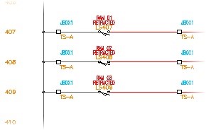
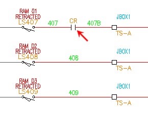
Now in this case, I am just using %n,
00:53
which is the line reference number.
00:55
So that's going to be mimicked then into the wire number.
00:58
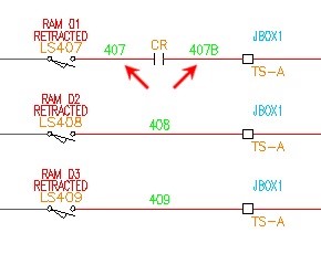
And if there are line breaks in the wires,
01:01
meaning there are additional components inserted on it,
01:04
that's when it will jump to the suffix setup.
01:07
So this is the key to making sure these
01:08
are set how you want them.
01:10
You also need to make sure that you have
01:11
where you want your wire numbers placed.
01:14
Do you want them above the wire, in line,
01:16
which you can actually define what the gap set up looks like?
01:19
So this is an intelligent gap, it's not
01:21
an actual break in the wire.
01:23
It's enough that Electrical knows
01:24
to just put that wire in there.
01:28
And if they're above or below, you
01:30
can actually have it put in leaders as needed.
01:32
You can either say you always want a leader,
01:35
Or if it's crammed in against other components
01:38
if it's a very busy ladder, you can have it do it as required.
01:42
So it'll see if there's a collision
01:43
and automatically throw a leader up to connect it to that wire.
01:47
You can also define whether or not
01:49
you want the wire numbers to stay centered on the wire
01:52
itself between the components that break that wire
01:55
or if you wanted it just a specific offset.
01:59
In this case, I'm going to leave it centered, my %n.
02:02
And we are ready to go.
02:04
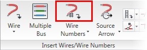
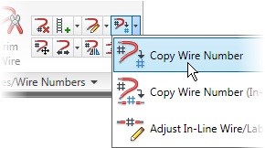
So now, all I'm going to do is click on the wire numbers
02:09
I'm going to say you tag and re-tag all.
02:12
It should always be safe to do a re-tag.
02:14
You should never feel uncomfortable
02:16
doing that assuming you're not manually editing wire numbers,
02:20
you're instead just throwing all of your wire numbers
02:22
and utilizing those replaceable parameters
02:25
we just talked about.
02:27
So when I do that, I'm going to then hit
02:29
the Drawing Wide in this case.
02:30
You could do Project Wide.
02:32
But for demonstration purposes, we're
02:34
just going to do this, Drawing Wide.
02:36
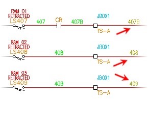
And you'll see it populate all of the wire numbers
02:42
Now one of the things we have not
02:43
talked about yet in Electrical is the use of layers
02:46
other than the wire layers themselves.
02:49
And there's a reason for that.
02:50
In AutoCAD Electrical, all layer properties are used.
02:54
There's a significant amount of layers
02:56
being utilized by the software but it's doing it on its own.
03:00
So it doesn't need you to tell it what layers to put things
03:03
on, it organizes it based off of the type of component or piece
03:07
of electrical that it is.
03:08
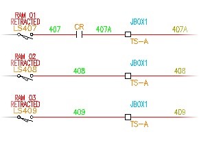
So if you notice, all of the wire numbers came in green.
03:11
They are on their own wire layer called wire numbers.
03:16
Now please take a moment to do the very quick exercise
03:19
on adding wire numbers.