00:08
Now that we've created a custom symbol,
00:10
we need to add it to our icon menu
00:12
so that we make sure that we can actually use it in the most
00:15
efficient way possible.
00:16
Not all that handy if you have to manually go
00:18
find it to insert it.
00:20
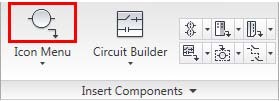
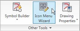
So the way to do that is to go to the icon menu wizard here.
00:24
This will open up a dialog box for us
00:27
to be able to edit which icon menu we
00:30
want to put this new symbol in.
00:31
In this case, I want to edit it right into my nfpa menu.
00:35
You could browse to find many of the other different types
00:38
of icon menus that AutoCAD Electrical comes with,
00:41
or you could create your own.
00:43
When I click OK, I'm going to be taken
00:45
into what looks just like my icon
00:47
menu I use when I'm inserting.
00:49
But if you notice, there's no buttons
00:51
at the bottom for actually inserting, rotating,
00:54
or doing any of the things we do in our normal insertion
00:58
Instead, we are actually live editing this menu.
01:02
So here, I can starter choose where
01:04
I want to put that symbol.
01:06
In this case, it was a relay so I'm
01:08
going to click into my relays in context
01:11
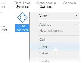
and then I'm going to right click in here
01:13
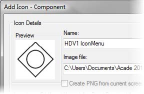
and say I want to add a new icon.
01:15
It is a component I will give it a name.
01:22
And then I will find that block and that png I just created.
01:28
So I'm going to go to my desktop,
01:36
and grab both of those.
01:38
They come in as opposed the W black
01:40
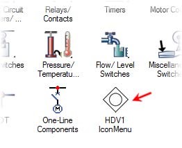
that it's connected to and the png image to show on screen.
01:44
When I click OK, there it is.
01:47
Now let's say that I want to be able to create a menu of all
01:51
of my own custom blocks.
01:54
If I want to do that out on the main page here,
01:57
I can right click and say Add New submenu.
02:00
I'll give it a name.
02:05
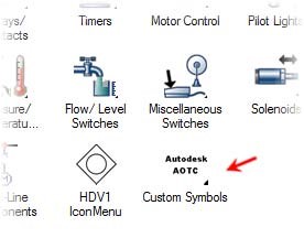
This may be your company name or whatever
02:07
else you want to put in there as your own custom symbols.
02:10
And then you can grab an image file
02:11
for what you want that to look like.
02:16
And then as soon as you grab that and bring it in,
02:18
you will see that as now a new menu.
02:20
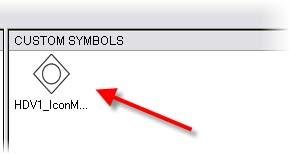
And then in here, you could add any of those additional custom
02:24
So had I not wanted to put the relay in my relay section
02:28
but instead in my own custom area, I can do that as well.
02:31
I could even copy and paste it and have it in both places.
02:35
So now you know how to add your own symbols
02:37
and your own submenus to your icon menu.
02:40
Please take a moment to do the exercise
02:43
on editing your icon menu.