00:08
Now, let's talk about terminals.
00:10
Terminals are another form of standard component
00:12
that we have with AutoCAD Electrical,
00:14
but there's a lot of additional information and nuances
00:17
that we can do with our terminals.
00:19
And the first thing I'm going to do
00:21
that's different than the last couple of times
00:23
we've gone to the Icon menu, is I'm
00:25
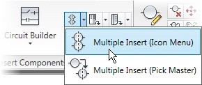
going to take the opportunity to do a multiple insert.
00:28
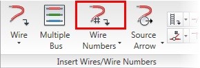
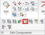
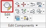
So if you look in our insert components panel here,
00:32
there is this multiple insert option.
00:34
It will launch the same dialog box
00:36
that we saw when we hit Inserts from the Icon menu,
00:41
but this time we actually have the ability to fenceline
00:45
draw where we want multiple components to be inserted.
00:48
It's a very fast way to add a lot of components at one time.
00:52
And terminals happen to be the type of components
00:54
we insert a lot of at one time.
00:57
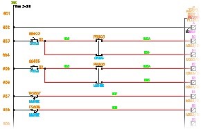
So now let's talk about terminals in general.
00:59
They are located right in the middle of the Icon menu.
01:04
And we have five different standard terminal
01:06
types that it comes with.
01:08
So in shape form, it's obviously square, round, hexagon,
01:12
diamond, or triangle.
01:14
Now, within every shape type, there
01:16
are four different kinds of terminals so we'll just
01:19
take square as an example.
01:21
Square by itself with nothing else on it
01:24
is what we would call a dummy terminal.
01:26
It's intelligent enough to break the wire,
01:28
but it doesn't carry any information on it
01:31
to make it an intelligent symbol.
01:33
It's really a placeholder.
01:34
The next one over is square with wire number,
01:37
this type of terminal takes on the wire number
01:42
of the wire it's inserted on.
01:44
It does not force a wire number change
01:46
as that wire passes through the terminal.
01:49
The next one takes on whatever value we want to give it.
01:53
A terminal number to be able to identify that terminal width,
01:56
but still does not force a wire number change
01:58
as it passes through it.
01:60
The final one carries a terminal number
02:03
as well as forcing a wire number change
02:05
as that wire passes through it.
02:08
Those are the four different kinds of terminals.
02:10
And that is true for all of the five different styles.
02:14
Now, I'm going to choose the one that I
02:16
want to use in this example, which I'm going to choose
02:18
diamond with a wire number.
02:21
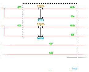
And it's going to ask me where do I want to fenceline.
02:24
So if you've ever drawn the fence tool within core AutoCAD,
02:28
this is allowing me to draw right through my wires.
02:31
Now, you may want to turn Ortho on so that you can make
02:34
sure they're lined up straight.
02:36
And then as I cut across it, it will not
02:38
insert because it's not crossing any wires when I go across.
02:43
So I can actually make a bit of a U-shape
02:46
here to an upside-down U, to be able to get all of the fence
02:52
Now, it's going to first drop the very first one
02:54
in from where I started to cross the wires.
02:56
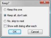
And it will ask me, do I want to keep this one
02:58
or do I want to skip to the next.
03:01
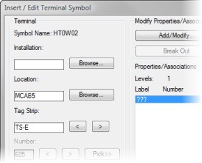
And then it opens up my insert terminal dialog box.
03:05
If your dialog box looks like this,
03:08
it's just because it's the first time you've ever opened it.
03:10
Make sure you click that little details button here
03:13
and you'll see an expanded terminal symbol box.
03:16
Now, this is different than our standard insert
03:18
at its component dialog box because there's
03:21
a lot of things unique to terminals built
03:23
into this particular menu.
03:27
First of all, we would want to talk about what location code
03:29
it's going on and what tag strip it's a part of.
03:32
Now, by default, it's choosing the tag strip TB that I have.
03:36
I can see a list of all of my existing terminal strips here
03:41
and the tags associated with those terminal strips, hence
03:45
If I take a look at those and I see
03:47
that I want to add it to an existing terminal strip
03:49
I could do that or I could start a brand
03:52
new terminal strip name, which I'm going to call mine T-demo.
03:56
Then my location code, I can either
03:58
browse for what location code I want to use
04:01
or I can just use what's existing in that dialog box.
04:04
Perhaps it was already pre-setup from the last time
04:06
I inserted terminals.
04:07
Now, the next thing to do is actually
04:09
choose the manufacturers that you want.
04:11
This particular terminal that's currently here
04:13
is just a single level terminal.
04:16
Perhaps you want to use a multilevel terminal.
04:19
If I go to catalog lookup and I search on all terminals--
04:25
so I'm just going to back this out--
04:27
and give a search for everything,
04:29
you can actually see all of the different terminal
04:31
types that exist in here.
04:33
And I can even search on things like multi-level.
04:36
So in this search dialogue, it's a bit like a Google search
04:39
where you can just type whatever you're looking for.
04:41
And I can say I want to find all multi-level terminals,
04:47
so that's going to search any column that I have here
04:50
to find that particular phrase inside any of these fields.
04:59
So I'm going to search through.
05:00
I can scroll, you can see all the multi-levels
05:02
that are listed in here.
05:04
And I'm going to grab this [INAUDIBLE] one.
05:13
And it'll notice, if for some reason
05:15
I had an item number already in here,
05:17
which I did because I cleared out the earlier terminal
05:20
and I see the item number needs to be updated,
05:23
it will automatically message me for that.
05:26
So it's going to clear it and tell me that I
05:27
could add a new item number.
05:29
We'll talk about item numbers when we actually
05:31
get to our panel drawings, but just start
05:33
keeping in mind that you could be editing
05:35
and utilizing item numbers even in your schematic placement.
05:38
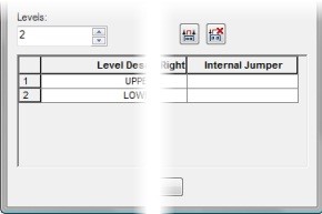
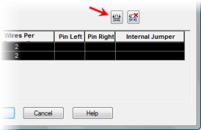
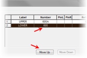
Now, if you notice, this was a three-level terminal.
05:43
So I now have a top, middle, and bottom set up to this.
05:48
And I can start adding terminals to this
05:50
to be associated as this multilevel terminal type.
05:54
If I click OK on here and I say that I want to--
05:58
I'm not going to map the symbol as we talked about.
06:00
My favorite part about the multi-add
06:02
is I can say keep all, don't ask.
06:05
And I can uncheck the show edit dialog box.
06:08
Because what it's going to do is it's
06:09
actually going to add all that same information
06:11
to every single terminal that it's placing.
06:14
So it's all been copied in there.
06:15
It's a very fast way to add multiple components
06:19
I don't need to hide the tags or the installations.
06:22
I'm going to leave those open, but that is an option.
06:26
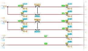
And now you'll see it.
06:27
Place all of those terminals and the information
06:33
that we have on those.
06:35
Easy is that and we have all of those terminals now placed.
06:38
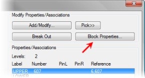
Now, we can here then start to edit our terminals.
06:42
So we can add information to these terminals.
06:45
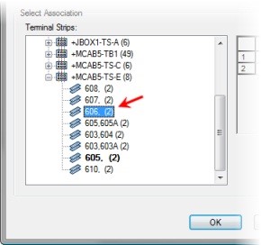
By right-clicking on them, you can see the different terminal
06:50
So there is association of terminals,
06:52
there is jumper information, and then
06:55
there's a few other additions to those association and jumpers.
06:58
Things like breaking those associations apart and then
07:01
even copying terminal properties.
07:04
Now, associating terminals is what's
07:05
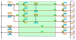
allows us to define the multi-level terminals.
07:09
In the schematics, they don't look multilevel.
07:11
They look like individual terminals,
07:13
but when we associate them to each other,
07:15
they become a part of that multilevel terminal.
07:18
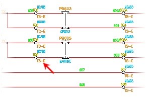
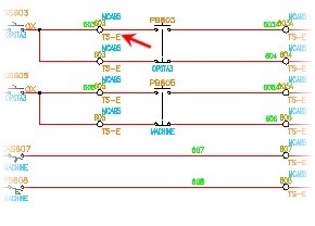
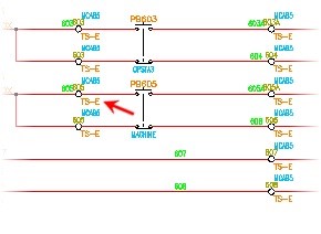
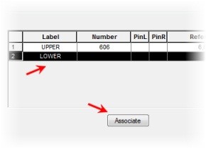
So, for instance, if I were to connect--
07:24
and I am going to just go in here and grab associate.
07:28
If I were to grab this terminal and this terminal and hit
07:35
Enter, you don't see it happen on screen,
07:38
it was happening down in the command prompt,
07:40
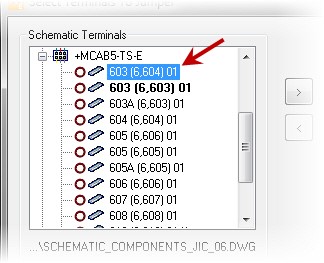
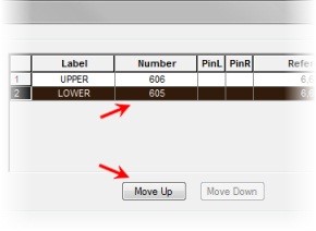
but when I right-click on it and I edit this component,
07:44
I can now see that 603 and
07:48
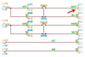
the levels of these terminals.
07:50
So they now know that is not just
07:52
its own independent terminal.
07:54
It's a part of this multilevel terminal.
07:57
Now, if I was actually jumpering something together,
08:01
we don't see the little jumper so people ask me about that.
08:03
You could draw a loop if you wanted to,
08:06
but we define that in the actual properties of the terminals.
08:10
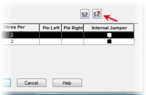
And then we can drive jumper charts
08:12
and other kinds of reporting tools like that
08:14
out in the panel drawings.
08:16
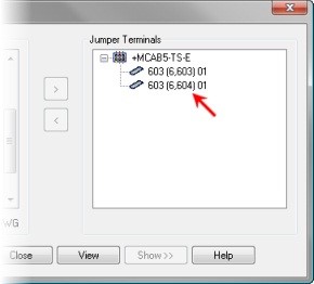
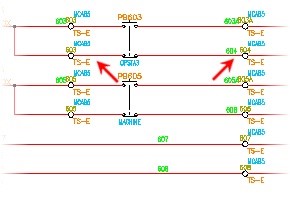
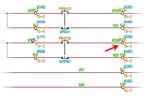
So if I were to right-click on this terminal
08:18
and I were to come down and say, Edit Jumper,
08:21
I can then choose this terminal and this terminal.
08:25
Hit Enter and you will see that they are jumpered together.
08:27
And then I can actually add catalog information
08:33
Please take a moment to do the insert terminals
08:36
and edit terminals exercise.