00:05
Now that we have looked at some of the core capabilities
00:07
and workflows for creating assets and using them within the digital factory model.
00:11
We're ready to explore how this integrates within the larger ecosystem of a factory planning project.
00:16
The modeling and layout tools are great,
00:18
but how can we efficiently collaborate and communicate in the context of the data we create.
00:23
Firstly as previously mentioned for all mechanical engineering designs,
00:27
especially if data volume increases, you can leverage tailored product data management solutions such as Vault,
00:33
which has even a factory specific configuration you can use in order to manage asset and layout data smoothly.
00:40
What we commonly see across industries is the use of Navisworks to aggregate all of the data,
00:44
including the factory layout created in AutoCAD and Inventor,
00:48
to have one federated file containing all discipline engineering data,
00:51
architectural models layout and equipment and even scanned as its representations of an existing factory.
00:59
we can run clash simulation to identify any interferences before they even become a problem in the real world.
01:06
And in different phases of the project,
01:08
perform design reviews and work through the digital factory model virtually even and even more.
01:15
If you would like to enable coordination within the cloud environment,
01:19
for example, to easily bring in external stakeholders and subcontractors,
01:23
you can do so by using Autodesk construction cloud.
01:26
It also enables you for elegant issue management capabilities, cloud based automated clash detections,
01:31
additional review workflows and project management and a number of other useful tools.
01:37
To come back to the engineering portion itself,
01:40
our development teams have been investing in an enhanced interoperability between Revit and Inventor,
01:44
allowing for workflows in both directions.
01:47
You can either reference Revit project file natively and associatively within Inventor using AnyCAD
01:53
with exactly the details you need in your context.
01:55
But you can also generate a native Revit project file from your assemblies
01:59
or digital factory model in this case and pass it on to colleagues
02:03
or teams working in Revit who might need the geometric context of everything within the factory for their work.
02:09
This functionality is available from inventor 2022 and newer.
02:15
All the pieces are coming together now.
02:18
You can choose in a somewhat modular manner which aspects and tools
02:22
would be most valuable to you for achieving optimized factory planning.
02:26
Whether it is creating layouts efficiently using the factory design utilities,
02:30
bringing in different discipline engineering data,
02:32
to aggregated into a federated model for always working in the context of the building itself or unlocking the closed loop,
02:39
cloud enabled coordination and collaboration across teams and companies from planning all the way to operation of the factory.
02:46
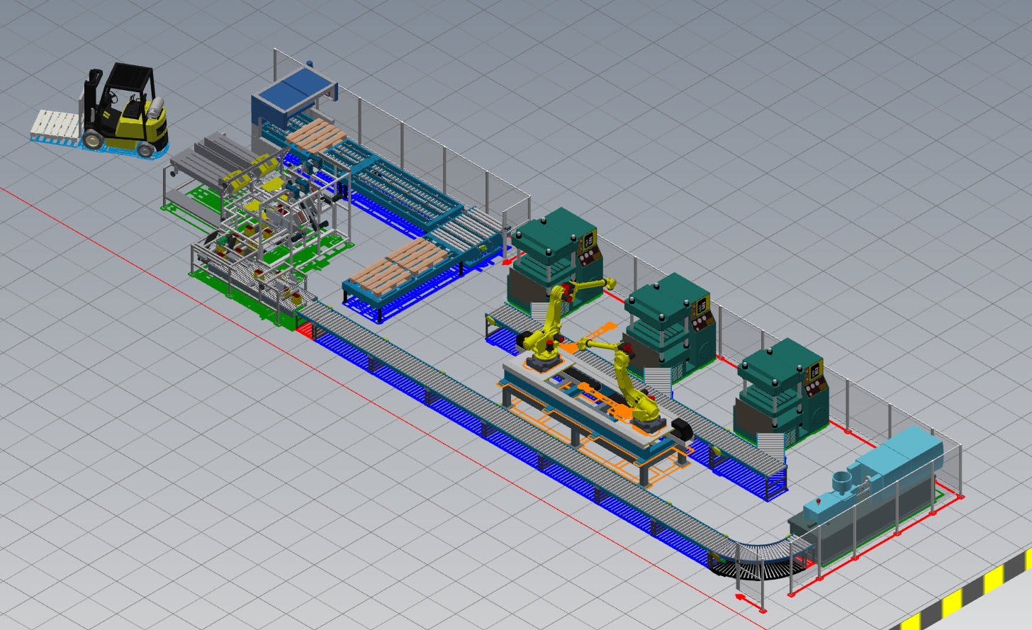
Let's finish up the presentation with looking at the ladder in a small demonstration.
02:52
Our customer provided us with the building model they had received from the architect,
02:56
a subcontractor already commenced working on the ventilation system, which we have linked into this file.
03:01
We would now like to use this information to make informed decisions on where to place
03:06
and where not to place our equipment in the production lines.
03:09
Within Inventor through the Assemble tab, we start the command to import CAD files
03:14
and navigate to the Revit project file which is stored in BIM 360 project shared with the subcontractors and customers.
03:21
We can easily do this via the desktop connector, basically a mirror of the cloud data within the file explorer level.
03:32
After finding our building model,
03:37
we open it and get the import dialog pop up.
03:41
we will have the choice of either referencing it via any CAD associatively
03:45
in order to be notified about updates within the Revit model
03:48
or we can translated into actual inventor files if we intend to make any changes to the geometry itself.
03:55
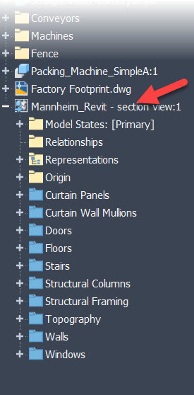
In this case we merely needed as a context reference.
03:58
So we select exactly the view we require
04:00
as well as the element categories that are relevant for us and confirm the import afterwards.
04:22
Since we work off a share coordinate system, which is crucial.
04:26
We can simply place the model at the origin and it will allow us to check for any obvious errors within the layout in work.
04:51
Let's now play through the other scenario.
04:54
We've got a release candidate for our production line
04:57
and the team working in Revit asked for it to check it against their building modifications.
05:02
They don't need any details regarding the equipment itself and we would like to protect our intellectual property.
05:07
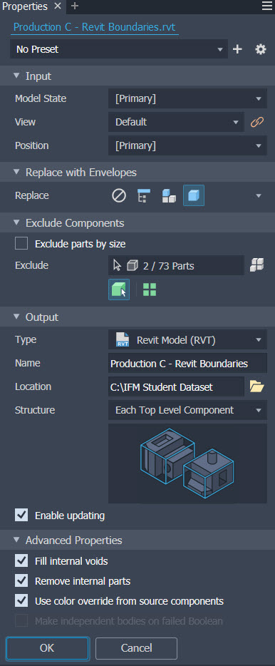
So the first step is again a step of simplification.
05:10
This time we reduced the complexity to a bare minimum.
05:13
Using the replace of an envelope function to get a bounding box representation of every part within the production line.
05:19
You can see how easily we can minimize the geometric level of detail.
05:25
After giving it a meaningful name to the generated .rvt file that we will be generated, we confirm to start the calculation.
05:36
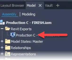
After its completion, a note with in the model browser gets created containing all our Revit exports
05:41
and we are ready to send it over to the requesting team.
05:52
this model can simply be linked into the main model again using origin
05:56
to origin as all parties work with the same reference coordinate system.
06:14
Let's now take it a level higher and look into the cloud.
06:24
We are within the document management module which contains all model files
06:27
as well as any other related data and relevant for the project.
06:31
Changing into the model coordination module will present us a screen to select models,
06:36
we would like to combine for coordination from within a previously set up coordination space.
06:42
Model files can be aggregated visually
06:45
but don't contribute to the automatic cloud clash detection are highlighted by icon left of their name.
06:51
Let's start with the building file itself.
06:52
Once loaded into the viewer, we can optionally load additional model file into the same view.
06:58
For visualization purposes, let's also append the other two production lines into the view.
07:14
we can then use various tools for measuring, annotating, sectioning and more in order to review the factory model.
07:32
Changing to the clashes tab on the left hand side will provide access
07:35
to all intersections were found between the contributing models.
07:38
This happens and updates automatically as we update our models.
07:42
Browsing through the found clashes and by a trusting some of the settings,
07:46
we noticed that some of them are in fact not actionable or not an issue,
07:49
so we can mark them accordingly as not an issue.
08:09
One clash however, definitely needs to be looked at, so we create an issue for it.
08:20
Mark its location within the view and enrich it with all necessary information
08:28
and assign it to the corresponding company role or specific user accordingly.
08:33
They receive a notification that an issue has been assigned to them,
08:37
open the latest Revit model from the cloud and check the issue through the issue management interface inside of Revit,
08:43
which is also available within Navisworks by the way.
08:48
After carefully reviewing the situation,
08:50
it is decided that the culprit wall can be removed and this you can be closed in order to be reviewed.
09:07
The updated Revit model can be save back to BIM 360.
09:22
To close the loop fully within inventor we get a notification that something has changed about the reference cloud file.
09:27
After fetching the latest file, we can see that also here, the wall is now removed.
09:34
Everyone being on the latest up to date data at all times.
09:38
This concludes an example of a coordination workflow on our digital factory model.
09:49
Lots of content, lots of tools I know.
09:52
Remember that many of the shown workflows are optional for you based on the value they potentially provide.
09:57
So you can assess and get started in a modular way,
10:00
for that and to come back to the core tools the factory design utilities,
10:04
I always like to share some tips and resources for getting started.
10:08
I encourage you to create a request from your IT department, a sandbox environment,
10:12
in order to test the asset creation and layout planning workflows on your data on your machines.
10:18
since it sometimes requires to run several tools in parallel and digital factory model can become quite large in file size.
10:26
It is always good to do a brief hardware check and read through the minimum system requirements,
10:30
which are found in one of the links I will share.
10:33
And lastly synchronizing layouts back and forth between 2D and 3D,
10:37
can require some time as well depending on the size of the layout.
10:40
So be mindful of doing so only when needed or finished with your work.
10:44
But remember to save frequently.
10:47
Here are some more links for general information, questions have you better related to this tool sets?
10:52
This concludes our introduction to the integrated factory modeling workflows,
10:56
I hope you enjoyed and got some insight for the details.