Step-by-step:
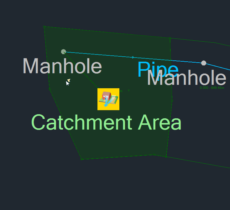
Catchment areas define which manhole rainfall will run off into, once it lands on the catchment surface. Designers should inspect surface data and background mapping to help them manually create polygons, and then assign those polygons to the relevant manhole.
For this example, starting in the northwest corner of the model, the assumption here is that all the rain that would fall into the area of this first polygon will drain into the first manhole. (The definition of the catchment boundary is a judgement that the designer of the system must make; it is not a function of the program.)
- On the ribbon, Plan tab, Modes panel, ensure that Snap is ON.
- From the Toolbox, ensure Select is active.
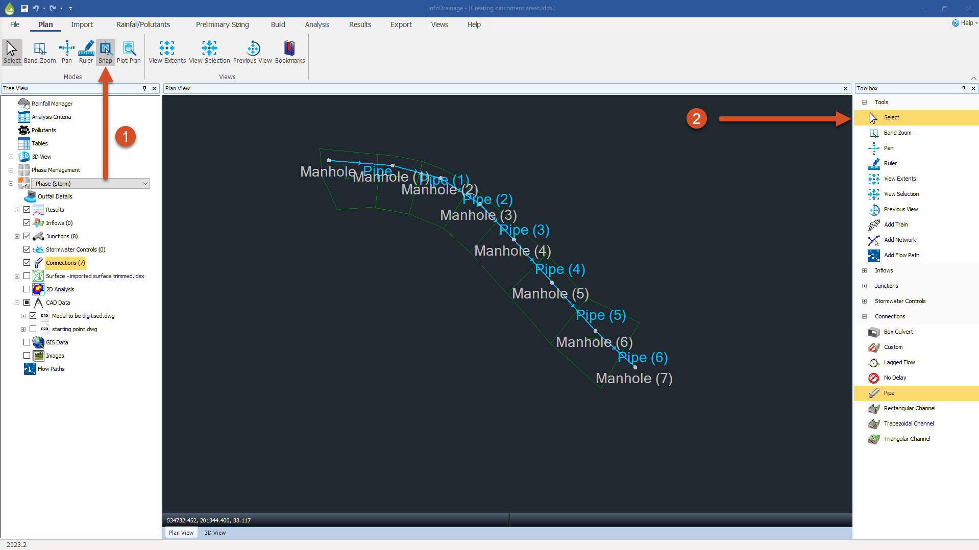
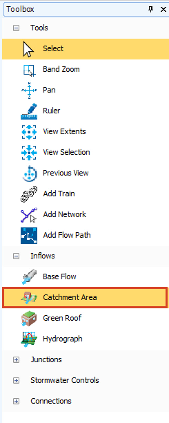
- Expand the Inflows node.
- Select the Catchment Area tool.
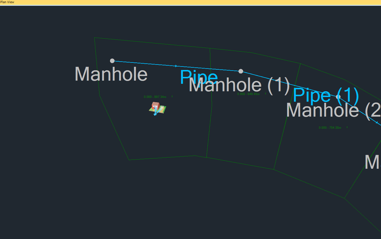
- Click and drag the Catchment Area symbol into the center of the first (upstream) polygon.
- Click at the first vertex in the top-left corner of the polygon.
- Move the cursor toward the next vertex.
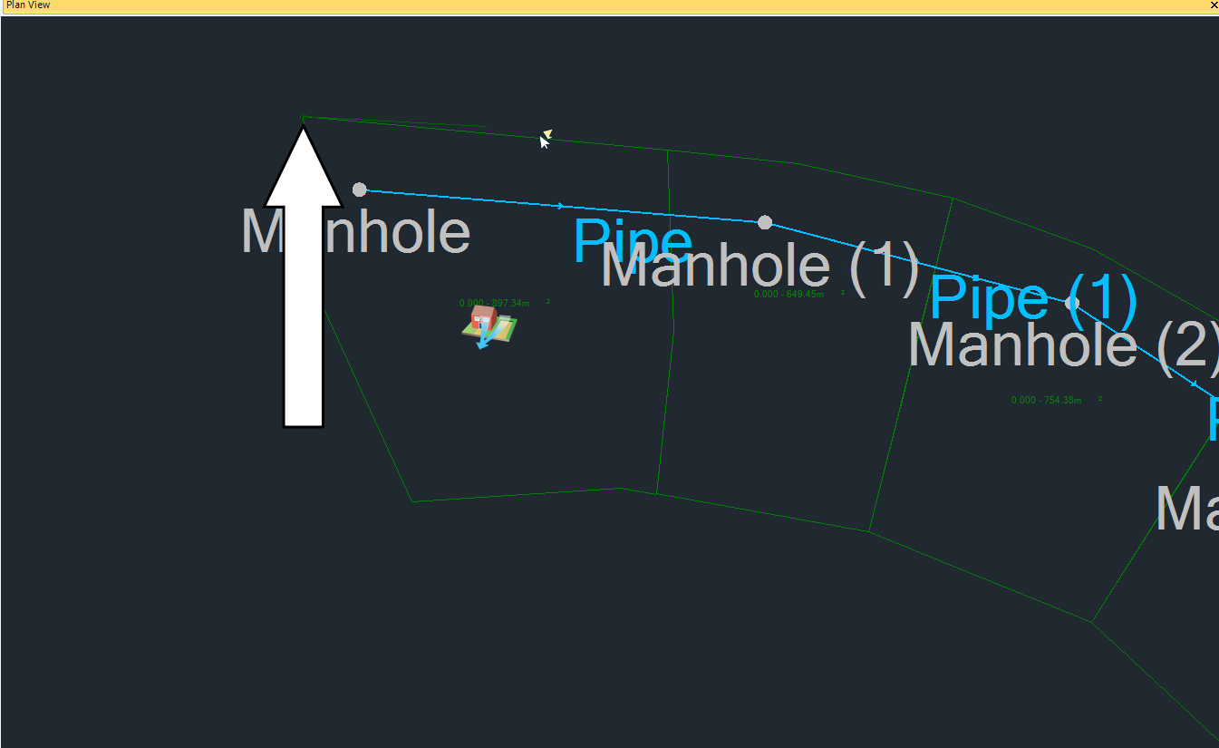
- Snap to that second vertex and click, and the first edge is created.
- Continue around the polygon, being sure to click at each vertex.
- When you reach the last vertex—not the starting vertex—you can right-click to end the command, and the polygon highlights as complete.
- Continue creating catchment areas for the remaining areas of the model.
- If you find that there is a vertex that is out of place, you can click and drag it back to the position it should be.
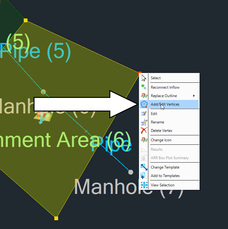
- To add a vertex, right-click a vertex and select Add/Edit vertices.
- To remove an extra vertex, click to highlight the vertex and press DELETE on your keyboard to remove it.
- In the Toolbox, click Select to end the command.
- To start again and recreate the catchment boundary, right-click on the catchment symbol and select Replace Outline.
- To change the manhole that the catchment area drains into, right-click within the catchment area and select Reconnect Inflow.
- Click the Select tool to end the command.


