Step-by-step
When working with a Civil 3D project file that is intended for work in InfoDrainage, after the drawing template has been configured and the coordinate system and parts lists have been set, the next step is to import the location data of the pipes and manholes that are to be created.
To import the location data of the pipes and manholes:
- In the Toolspace, click the Prospector tab.
- Ensure the file Surfacecreated.dwg is open in a new drawing tab, if it is not already.
- Open the file Pipe outline.dwg in a new drawing tab.
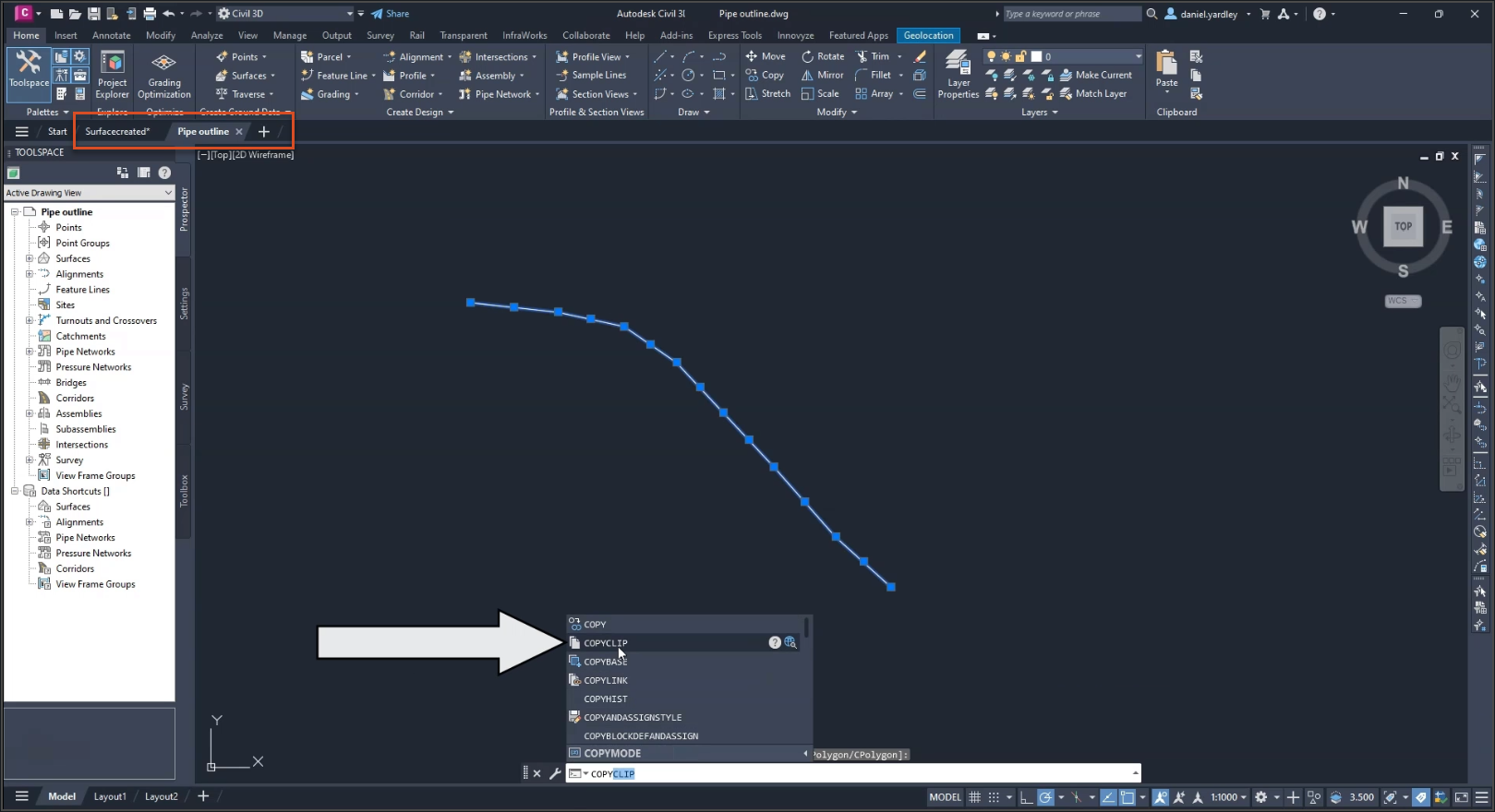
- In the Pipe outline drawing, highlight all the pipes to select them.
- Copy them to the clipboard.
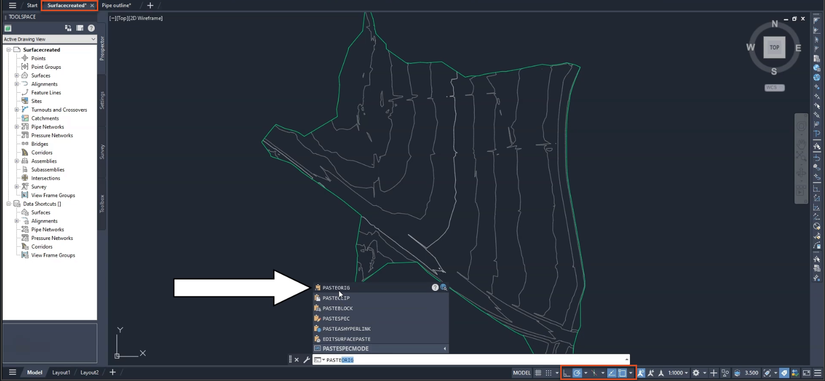
- Use PASTEORIG to paste the pipes into the Surfacecreated.dwg drawing. (The PASTEORIG command allows for the origin to align so that the pipes are placed correctly.)
- Turn the Snap tools ON.
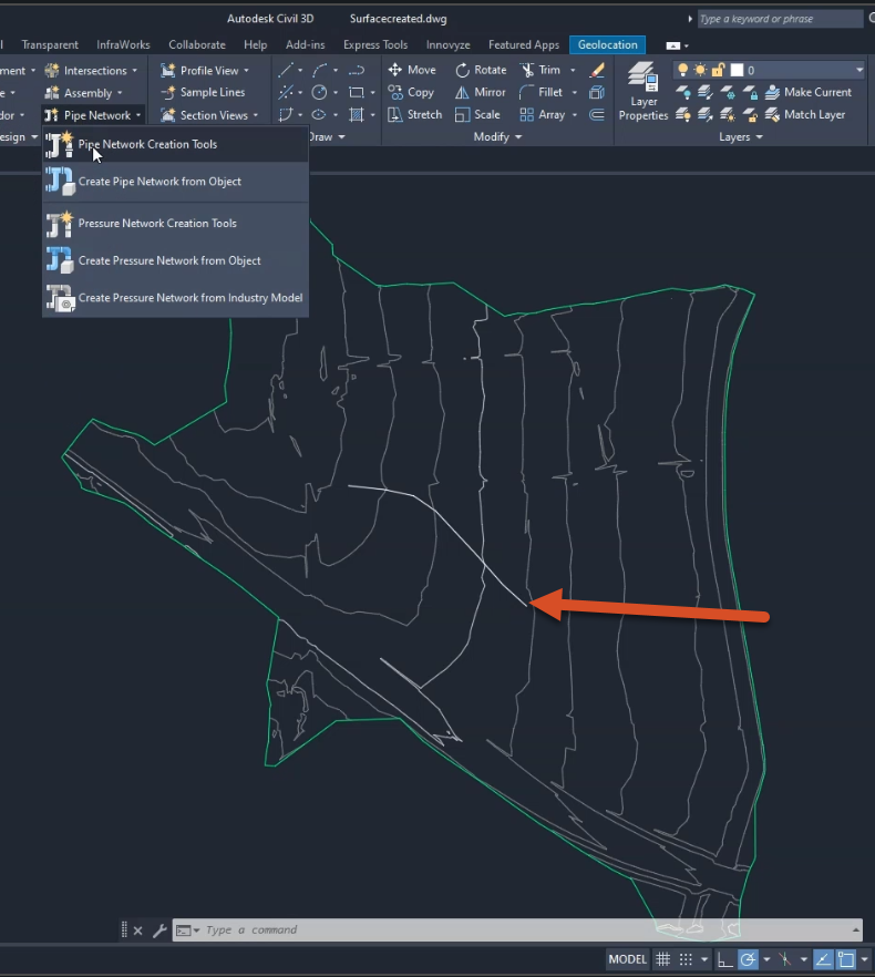
- On the ribbon, Home tab, Create Design panel, expand the Pipe Network drop-down and select Pipe Network Creation Tools.
Or, in the Prospector tree, expand the Pipe Networks collection, then right-click the Networks collection, and click Create Pipe Network By Layout.
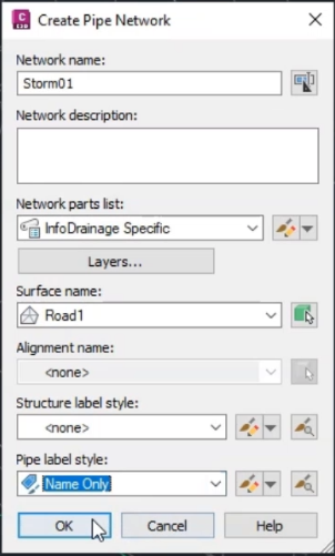
- In the Create Pipe Network dialog box, enter a Network name. For this exercise, name it “STORM01”.
- Optionally, enter a description for the network.
To specify the parts list associated with this pipe network:
- Under Network parts list, expand the drop-down and select InfoDrainage specific.
- Under Surface name, expand the drop-down and select Road1.
- Keep the Alignment name set to none.
- Keep the Structure label style set to none.
- For the Pipe label style, select Name Only.
- Click OK.
The Network Layout Tools toolbar appears. To select parts from the Pipe List and Structure List:
- Expand the Structure List drop-down and select Concentric structures as the structure type.
- Expand the Pipe List drop-down and select 100 mm Concrete Pipe (if not already selected) as the pipe type.
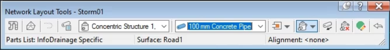
Note: It does not matter what size is selected for the structure and pipe elements, as these will be designed in InfoDrainage.
In the drawing, create the network:
- Ensure the Snap tools are ON.
- Zoom into the drawing.
- Hover the cursor over the end of the pipe network, and the manhole highlights.
- Click to create the first structure.
- Continue clicking along the line; clicking every manhole.
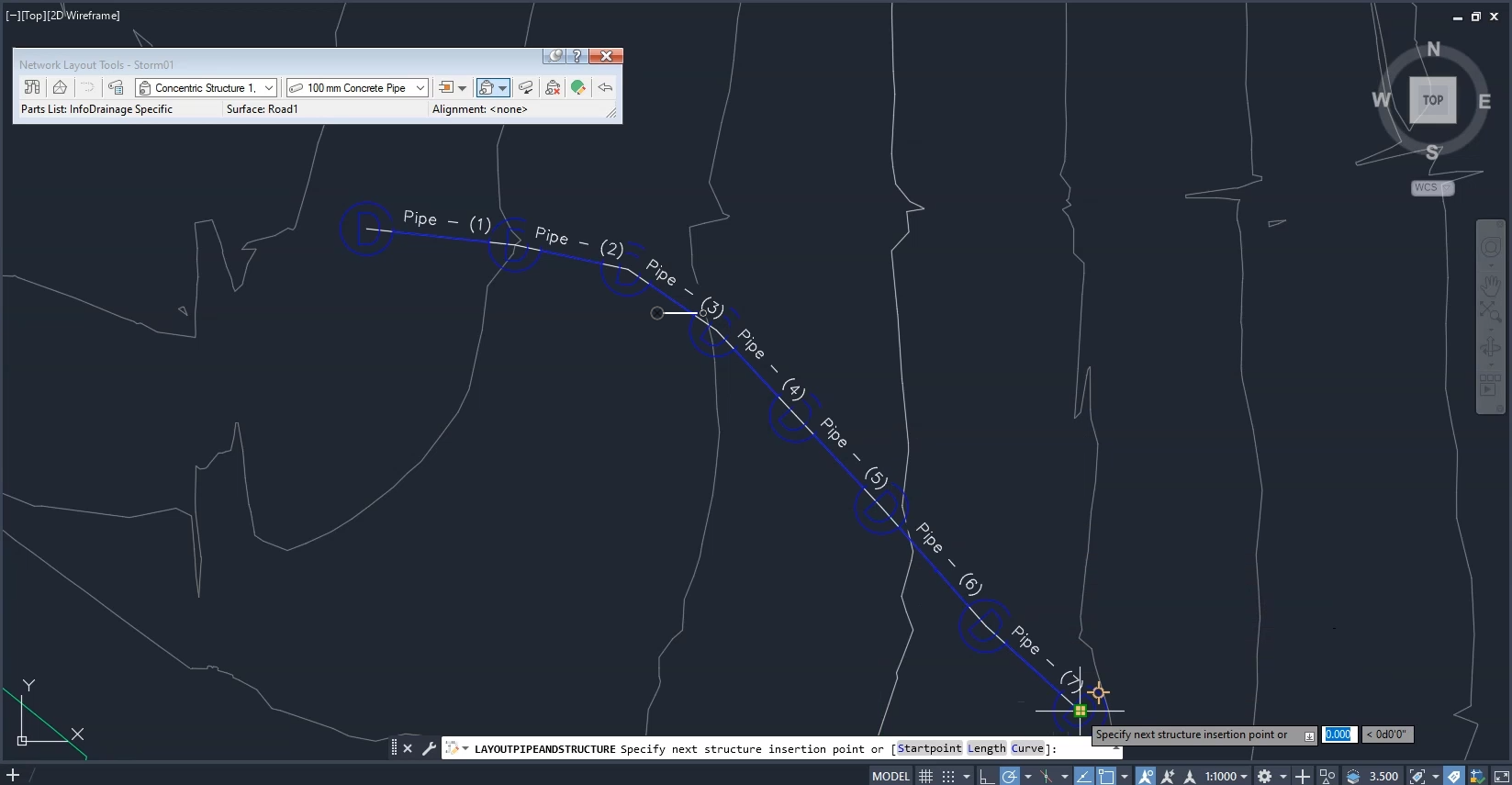
- Press ESC to finish.
The pipe network is complete.
- Save the file as “Pipesandmanholes.dwg”.


