Completing a GIS Exchange Cluster Update

00:03

Once you have set up a GIS update for new and

00:06

updated elements and compared the elements to be added or updated,

00:10

you can run the exchange clusters and complete the model update

00:14

to begin.

00:15

Double click the desired project dot APR X file to open

00:18

Agis Pro.

00:20

Once the project starts,

00:22

click the info water pro tab to open the info water pro ribbon

00:26

in the project panel, click initialize

00:29

first, create two selection sets, one for the new pipes and one for the updated pipes

00:36

on the info water pro ribbon edit panel,

00:39

click G I S gateway

00:42

in the GIS gateway dialogue, click load

00:47

in the load data from GIS layer or table dialog.

00:50

Click the more button next to the updated facility's selection set field

00:55

in the selection set, dialogue, click new,

00:58

enter a new id of new underscore G I S underscore pipes, comma new G I S pipes

01:06

and then click, OK,

01:09

click new again.

01:11

Enter a new id of updated underscore pipes, comma updated GS pipes

01:17

and click, OK.

01:19

Make sure that updated pipes is selected in the ID list and click OK.

01:25

This adds the selection set to the

01:26

updated facility's selection set field automatically and

01:30

saves all pipes updated by the GIS exchange cluster into this selection set.

01:36

Now click more beside the newly created facilities, selection set field

01:41

in the id field,

01:43

select the new G I S pipes selection set you just created then click OK.

01:50

This saves all new GS pipes added to the model

01:53

by the GIS exchange cluster into this selection set.

01:57

Now that both GIS

01:58

clusters and selection sets are complete. You are ready to load the data

02:03

under select info exchange cluster,

02:05

press control and multi select the clusters pipes,

02:09

new pipe import

02:10

and pipe update GS pipe update.

02:14

Make sure that only those two clusters are

02:16

highlighted because only those will be run,

02:19

click load.

02:21

You may see several messages in the message

02:23

board regarding elements already in the model database.

02:26

When the pipes cluster is run,

02:28

this is because most of the pipes are already in the model

02:32

when the exchange is complete.

02:33

And you see data exchange succeeded in the message board.

02:36

You can close the load data from GIS layer or table and GIS

02:40

gateway dialogs.

02:42

You can now load the new and updated pipes into the domain

02:46

on the info water pro ribbon

02:48

in the domain panel. Click domain manager,

02:52

click clear to clear the active domain

02:57

in the element source group,

02:58

click selection set and then expand the drop down and select updated pipes,

03:03

updated G I S pipes

03:05

and then click add

03:07

close the domain manager and review the selected features.

03:11

The updated pipes appear in red in the map

03:14

on the info water pro ribbon edit panel,

03:17

click select and select a few of the updated pipes.

03:22

Use the model explorer attribute tab to

03:25

review imported attribute data for these pipes.

03:29

Open the domain manager again,

03:32

click clear to clear the active domain

03:36

in the element source section. Pick selection set,

03:40

use the drop down list to select new G I S pipes, new G I S pipes

03:45

and click add

03:47

close the domain manager and review the selected features

03:52

on the info water pro ribbon

03:54

in the edit panel, click select

03:56

and select a few of the new pipes in the map.

04:00

Use the model explorer attribute tab to review

04:03

imported attribute data for these new pipes.

04:06

You can see that these pipes were imported

04:08

without roughness and start or end node values.

04:12

So you will need to add these features to finish the import

04:16

on the info water pro ribbon edit panel, click DB editor,

04:23

expand the element hydraulic data folder and

04:25

select the pipe hydraulic modeling data table

04:31

under data scope enable domain then click OK.

04:36

For this exercise, you should see three pipes listed in the DB editor,

04:41

click the roughness column header. So the entire column is highlighted

04:46

right, click the column header and select block editing

04:52

in the block, edit dialogue set the operation to set equal and the value to 110

04:59

click. OK?

05:01

A roughness value. Of 110 is added to the three pipes,

05:06

click save and then exit

05:11

in the model explorer on the command center tab expand the

05:14

utilities and connectivity folders and double click fill pipe connectivity.

05:21

This tool populates the start and end nodes for pipes

05:25

enable apply to domain

05:28

and then click fill

05:31

zoom in and select one of the new pipes in the domain.

05:34

So you can see its data in the model explorer attribute tab

05:39

note that the start node, end node and roughness fields are now populated.

05:45

This data is required for running simulations.

05:49

If you did not correct this and try to run a standard simulation, it would fail,

05:53

save the project.

Video transcript

00:03

Once you have set up a GIS update for new and

00:06

updated elements and compared the elements to be added or updated,

00:10

you can run the exchange clusters and complete the model update

00:14

to begin.

00:15

Double click the desired project dot APR X file to open

00:18

Agis Pro.

00:20

Once the project starts,

00:22

click the info water pro tab to open the info water pro ribbon

00:26

in the project panel, click initialize

00:29

first, create two selection sets, one for the new pipes and one for the updated pipes

00:36

on the info water pro ribbon edit panel,

00:39

click G I S gateway

00:42

in the GIS gateway dialogue, click load

00:47

in the load data from GIS layer or table dialog.

00:50

Click the more button next to the updated facility's selection set field

00:55

in the selection set, dialogue, click new,

00:58

enter a new id of new underscore G I S underscore pipes, comma new G I S pipes

01:06

and then click, OK,

01:09

click new again.

01:11

Enter a new id of updated underscore pipes, comma updated GS pipes

01:17

and click, OK.

01:19

Make sure that updated pipes is selected in the ID list and click OK.

01:25

This adds the selection set to the

01:26

updated facility's selection set field automatically and

01:30

saves all pipes updated by the GIS exchange cluster into this selection set.

01:36

Now click more beside the newly created facilities, selection set field

01:41

in the id field,

01:43

select the new G I S pipes selection set you just created then click OK.

01:50

This saves all new GS pipes added to the model

01:53

by the GIS exchange cluster into this selection set.

01:57

Now that both GIS

01:58

clusters and selection sets are complete. You are ready to load the data

02:03

under select info exchange cluster,

02:05

press control and multi select the clusters pipes,

02:09

new pipe import

02:10

and pipe update GS pipe update.

02:14

Make sure that only those two clusters are

02:16

highlighted because only those will be run,

02:19

click load.

02:21

You may see several messages in the message

02:23

board regarding elements already in the model database.

02:26

When the pipes cluster is run,

02:28

this is because most of the pipes are already in the model

02:32

when the exchange is complete.

02:33

And you see data exchange succeeded in the message board.

02:36

You can close the load data from GIS layer or table and GIS

02:40

gateway dialogs.

02:42

You can now load the new and updated pipes into the domain

02:46

on the info water pro ribbon

02:48

in the domain panel. Click domain manager,

02:52

click clear to clear the active domain

02:57

in the element source group,

02:58

click selection set and then expand the drop down and select updated pipes,

03:03

updated G I S pipes

03:05

and then click add

03:07

close the domain manager and review the selected features.

03:11

The updated pipes appear in red in the map

03:14

on the info water pro ribbon edit panel,

03:17

click select and select a few of the updated pipes.

03:22

Use the model explorer attribute tab to

03:25

review imported attribute data for these pipes.

03:29

Open the domain manager again,

03:32

click clear to clear the active domain

03:36

in the element source section. Pick selection set,

03:40

use the drop down list to select new G I S pipes, new G I S pipes

03:45

and click add

03:47

close the domain manager and review the selected features

03:52

on the info water pro ribbon

03:54

in the edit panel, click select

03:56

and select a few of the new pipes in the map.

04:00

Use the model explorer attribute tab to review

04:03

imported attribute data for these new pipes.

04:06

You can see that these pipes were imported

04:08

without roughness and start or end node values.

04:12

So you will need to add these features to finish the import

04:16

on the info water pro ribbon edit panel, click DB editor,

04:23

expand the element hydraulic data folder and

04:25

select the pipe hydraulic modeling data table

04:31

under data scope enable domain then click OK.

04:36

For this exercise, you should see three pipes listed in the DB editor,

04:41

click the roughness column header. So the entire column is highlighted

04:46

right, click the column header and select block editing

04:52

in the block, edit dialogue set the operation to set equal and the value to 110

04:59

click. OK?

05:01

A roughness value. Of 110 is added to the three pipes,

05:06

click save and then exit

05:11

in the model explorer on the command center tab expand the

05:14

utilities and connectivity folders and double click fill pipe connectivity.

05:21

This tool populates the start and end nodes for pipes

05:25

enable apply to domain

05:28

and then click fill

05:31

zoom in and select one of the new pipes in the domain.

05:34

So you can see its data in the model explorer attribute tab

05:39

note that the start node, end node and roughness fields are now populated.

05:45

This data is required for running simulations.

05:49

If you did not correct this and try to run a standard simulation, it would fail,

05:53

save the project.

Video quiz

Required for course completion

After completing a GIS exchange cluster update, why is it important to check the attribute data and make corrections for all newly imported or updated features?

(Select one)
Select an answer

1/1 questions left unanswered

Step-by-step:

Once you have set up a GIS update for new and updated elements, and compared the elements to be added or updated, you can run the exchange clusters and complete the model update.

  1. Open the appropriate .aprx file in ArcGIS Pro.
  2. From the ribbon, InfoWater Pro tab, Project panel, click Initialize.

Create two selection sets:

  1. On the ribbon, InfoWater tab, Edit panel, click GIS Gateway.
  2. In the GIS Gateway dialog box, click Load.
    The entire InfoWater Pro interface, showing the GIS Gateway dialog box open in front of the map view, with Load called out.
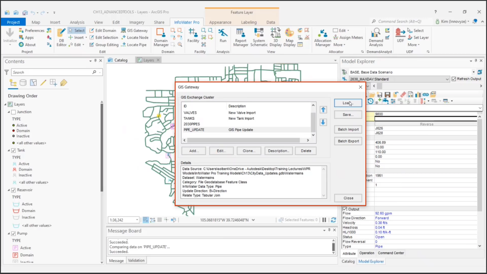
  3. In the Load Data from GIS Layer or Table dialog box, next to the Update Facilities Selection Set drop-down, click More ().
    The Load Data from GIS Layer or Table dialog box with the More button highlighted.
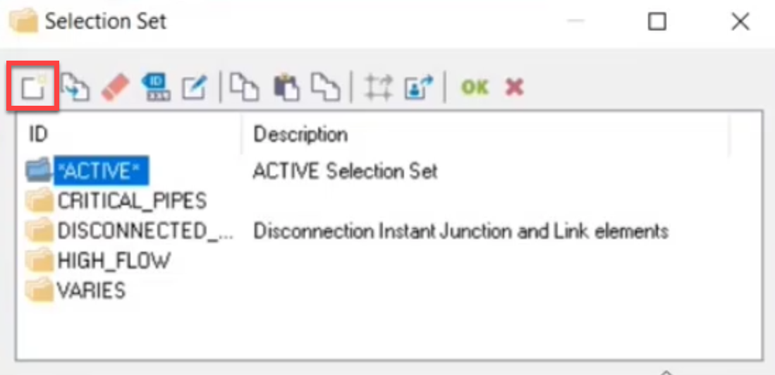
  4. In the Selection Set dialog box, click New.
    The Selection Set dialog box with the New command called out.
  5. In the New Selection Set popup, New ID field, type “NEW_GIS_PIPES, New GIS Pipes”.
  6. Click OK.
  7. In the Selection Set dialog box, click New again.
  8. In the New Selection Set popup, New ID field, type “UPDATED_PIPES, Updated GIS Pipes”.
  9. Click OK.
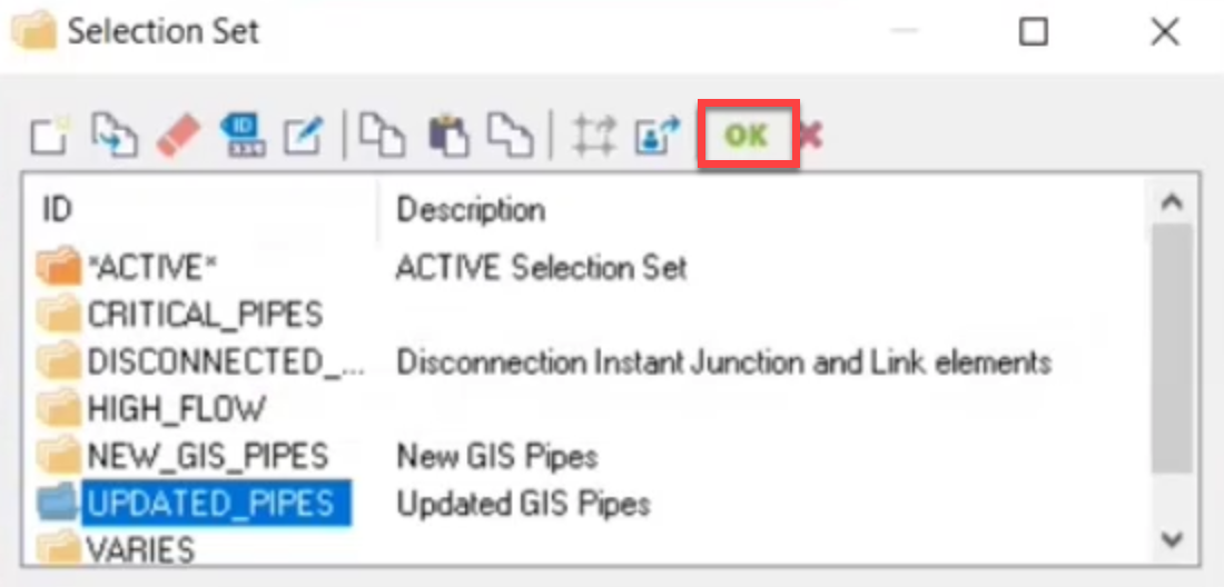
  10. In the Selection Set dialog box, ID list, select UPDATED_PIPES.
  11. Click OK.
    The Selection Set dialog box with UPDATED_PIPES selected, and the OK command highlighted.

This adds the selection set to the Updated Facilities Selection Set field automatically and saves all pipes updated by the GIS exchange cluster into this selection set.

  1. In the Load Data from GIS Layer or Table dialog box, next to Newly Created Facilities Selection set, click More ().
  2. In the Selection Set dialog box, ID list, select NEW_GIS_PIPES.
  3. Click OK.

This saves all new GIS pipes added to the model by the GIS exchange cluster into this selection set.

To load the data:

  1. In the Load Data from GIS Layer or Table dialog box, under Select Info Exchange Cluster, on your keyboard, press CTRL and multi-select the clusters PIPES, NEW Pipe Import and PIPE_UPDATE, GIS Pipe Update.
  2. Click Load.
    The Load Data from GIS Layer or Table dialog box with both clusters multi-selected and Load highlighted.

Note: Several messages may appear in the Message Board regarding elements already in the model database when the Pipes cluster is run. This is because most of the pipes are already in the model.

  1. When the exchange is complete, and you see “Data Exchange succeeded” in the Message Board, you can close both the Load Data from GIS Layer or Table and GIS Gateway dialog boxes.

To load the new and updated pipes into the domain:

  1. On the ribbon, InfoWater Pro tab, Domain panel, click Domain Manager.
  2. In the Domain Manager, click Clear to clear the active domain.
  3. For the Element Source, enable Selection Set.
  4. Expand the Selection Set drop-down and select UPDATED_PIPES, Updated GIS Pipes.
  5. Click Add.
    The Domain Manager dialog box with the settings configured and the Clear and Add buttons highlighted.
  6. Close the Domain Manager.
  7. Review the selected features. Updated pipes appear red in the map.
    The map view, with the new pipes showing within the circled area and one highlighted pipe about to be selected.
  8. On the InfoWater Pro ribbon, Edit panel, click Select.
  9. In the map, select an updated pipe.
  10. In the Model Explorer, Attribute tab, review the imported attribute data for the pipe.
    The Model Explorer, Attribute tab with updated information displayed regarding a selected pipe.
  11. Open the Domain Manager
  12. Clear the active domain.
  13. For the Element Source, select Selection Set.
  14. Expand the Selection Set drop-down and select NEW_GIS_PIPES, NEW GIS Pipes.
  15. Click Add.
  16. Close the Domain Manager.
  17. Review the selected features.
  18. Select an updated pipe.
  19. Review its imported attribute data in the Model Explorer.
    The Model Explorer, showing the selected pipe data and highlighting the Start Node, End Node, and Roughness values to show they are missing.

Notice that these pipes were imported without roughness and start or end node values, so you will need to add these features to finish the import.

To add a Roughness value to the three pipes:

  1. In the InfoWater Pro ribbon, Edit panel, select DB Editor.
  2. In the Open Table dialog box, select Element Hydraulic Data > Pipe Hydraulic (Modeling) Data.
  3. Under Data Scope, enable Domain.
  4. Click OK.
    The Open Table dialog box with the Pipe Hydraulic (Modeling) Data selected, Domain selected as the Data Scope, and the OK command highlighted.
  5. In the DB Editor, select the Roughness column header so the entire column is selected.
  6. Right-click the column header and select Block Editing.
    The DB Editor dialog box with the Roughness column selected, the menu displayed, and Block Editing called out and selected.
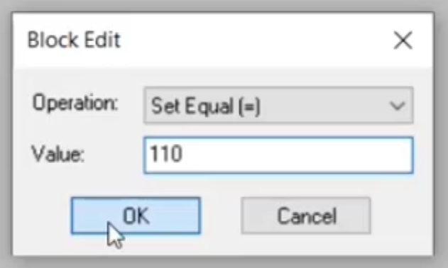
  7. In the Block Edit dialog box, set Operation to Set Equal (=).
  8. Set Value to 110.
  9. Click OK.
    The Block Edit dialog box with the Operation and Value set.

A Roughness value of 110 is added to the three pipes.

  1. In the DB Editor, click Save.
  2. Click Exit.

To populate the start and end nodes for the three pipes:

  1. In the Model Explorer, Command Center tab, expand Utilities > Connectivity.
  2. Double-click Fill Pipe Connectivity.
    The Model Explorer, Command Center with Utilities and Connectivity expanded, and Fill Pipe Connectivity called out.
  3. In the Fill Pipe Connectivity dialog box, enable Apply to Domain.
  4. Click Fill.
    The Fill Pipe Connectivity dialog box with Apply to Domain enabled and highlighted and the Fill button selected and highlighted.
  5. In the map, zoom in and select one of the new pipes.
  6. Review its data in the Model Explorer, Attribute tab.
    The Model Explorer, Attribute tab with the Start Node, End Node, and Roughness values highlighted, as now they are all filled in.

Note: The Start Node, End Node, and Roughness fields are all now populated.

IMPORTANT: This data is required for running simulations. If you did not correct this and tried to run a standard simulation, it would fail.

  1. Save the project.
Was this information helpful?