00:04
Info, Water Pro's pressure zone manager or PCM is a tool to interactively define,
00:09
verify and color code each pressure zone in a water distribution system model.
00:15
The PCM accelerates hydraulic diagram designs
00:18
of existing and proposed pressure zones
00:20
and helps ensure accuracy on projects
00:23
that feature frequent updates and revisions.
00:26
Pressure zone boundaries are based on hydraulic
00:28
elements in the model such as pumps,
00:30
valves, and closed pipes.
00:34
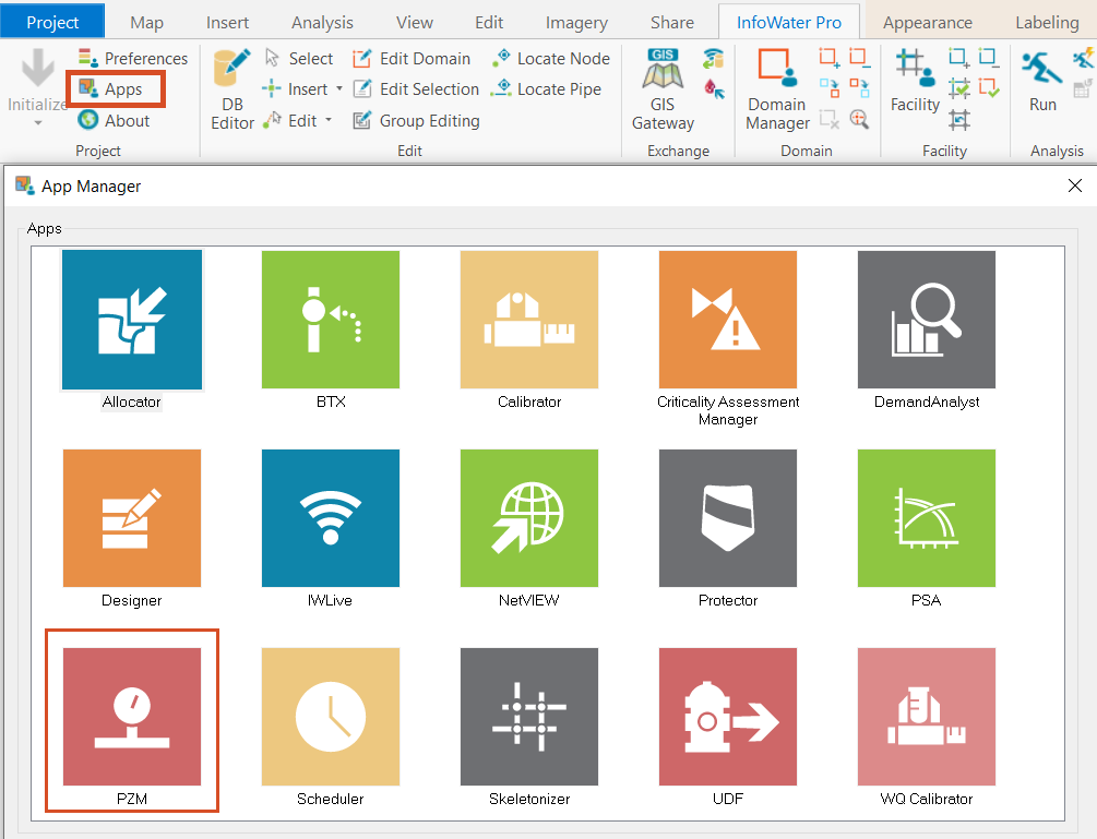
The pressure zone manager can be accessed from the info Water Pro
00:37
app manager in the project panel of the info Water Pro ribbon.
00:41
Once you click new the pressure zone wizard guides
00:44
you through the steps to set up the analysis procedure
00:49
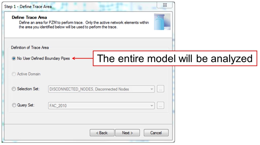
Step one define the trace area, you specify the area for the analysis.
00:54
The entire model or a subset of the model can be used for zone boundary analysis.
00:60
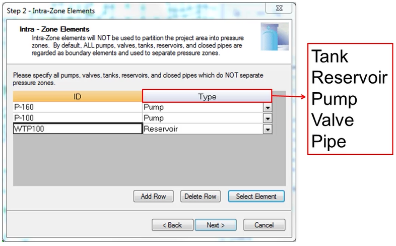
The second page is step two designate intra zone elements.
01:04
Here you add rows as necessary to ignore
01:07
specified elements as boundary elements such as valves,
01:11
reservoirs, pumps or closed pipes. During the trace analysis
01:17
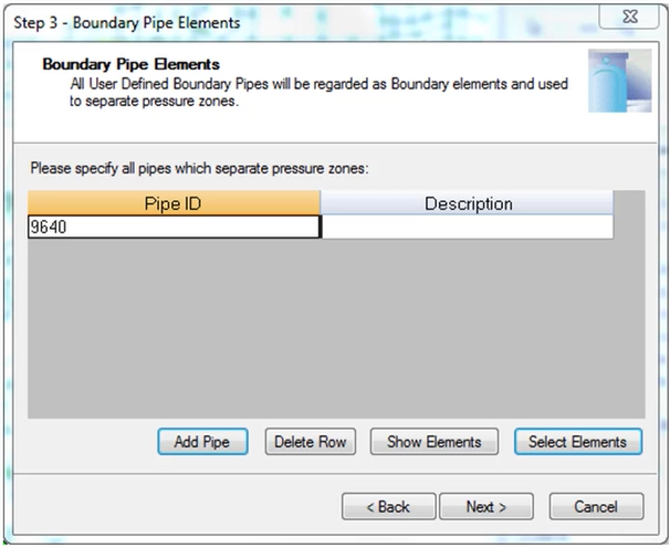
for step three specify boundary elements,
01:20
you can list pipes in this table that will
01:22
act as boundary elements during the trace analysis,
01:26
this can be useful to define a pressure zone by
01:28
political or geographic boundaries rather
01:31
than by pressure considerations alone.
01:34
In step four, customize zone information,
01:37
you can assign names and descriptions to pressure zones.
01:40
If this feature is not used,
01:42
then the pressure zone manager names pressure zones by default as PZ one
01:50
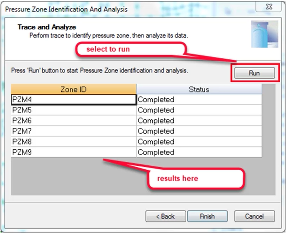
On the last page, step five, pressure zone identification and analysis,
01:55
you click run to start the pressure zone trace analysis
01:58
as each zone is analyzed.
02:00
The zone id is displayed as well as the status of the trace operation.
02:05
Upon completion of the analysis,
02:06
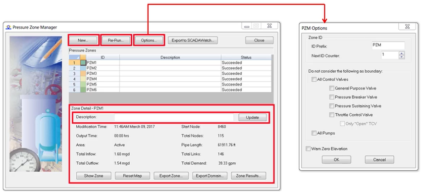
click finish to return to the pressure zone manager
02:10
from here. You can review details for each pressure zone.
02:14
Click the id field for any pressure zone,
02:16
then click show zone to display the color coded zone in the map
02:21
information about the zone appears in the P Z M such as total inflow outflow
02:26
nodes and pipe length in the zone.
02:30
For more detailed reports, click zone results.
02:33
This pressure zone results report includes the following information.
02:37
The hydraulic profile diagram displays summary information
02:41
along with elements that feed the zone.
02:44
The hydraulic profile schema provides summary information as well as inflow
02:48
and outflow from each element feeding or leaving the zone.
02:53
The zone summary provides a list of details for the selected pressure zone.
02:58
Boundary elements displays all boundary elements
03:00
associated with the selected pressure zone.
03:03
After analyzing the PCM results,
03:06
you may want to make changes to the pressure zones such as merging two zones into one.
03:12
you can rerun the pressure zone wizard and again
03:15
define intra zone elements for the PCM to ignore.
03:19
There are also various ways to export save and share PM result data
03:24
within the pressure zone results dialogue, you can do the following
03:29
create a PCM summary to view and print summary data,
03:33
save zone data to a CSV or file
03:37
and export to DX F to export the hydraulic profile to a CAD drawing
03:43
in the pressure zone manager dialogue.
03:45
You can export zone to create a selection set from the currently selected zone
03:51
export domain to add the currently selected zone to the domain
03:55
and export to info 360 to add the currently selected data to info 360.