00:03
Depending on your model,
00:04
you may have pipes that legitimately run in
00:06
parallel between nodes in your water distribution system.
00:11
But sometimes parallel pipes can occur as a result of duplication.
00:15
So it is important to review these areas.
00:19
Parallel pipes are identified as pipes sharing the same start and
00:22
end nodes and are not required to share identical vertices.
00:28
You can use the locate slash fix parallel pipes
00:30
tool to review these locations and fix any errors
00:35
to begin. Double click the desired project dot APR X file to open Argi
00:42
Once the project starts,
00:43
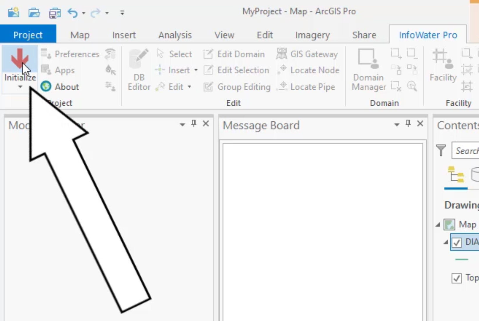
click the info water pro tab to open the info water pro ribbon
00:49
in the project panel, click initialize
00:53
to add all parallel pipes to the domain from
00:56
the command center tab in the model explorer,
00:58
expand the utilities network review slash fix, locate parallel pipes,
01:03
folders and then double click show as domain.
01:09
The location of the parallel pipes is found
01:13
to zoom in on the location
01:15
on the info water pro ribbon
01:17
domain panel, select the zoom to domain tool.
01:21
When you examine the network configuration,
01:24
notice that one pipe is highlighted in red,
01:27
you can then redraw the pipe with false vertices. So you can see the parallel pipes.
01:33
It is helpful in these cases to turn on the labels to see the node ids
01:39
from the contents panel,
01:40
right, click junction and select label
01:44
on the info water pro ribbon
01:46
in the edit panel, expand the edit dropdown and select redraw pipe.
01:53
Select the pipe to be redrawn.
01:55
You can see that it flashes blue, signifying that it is selected to be redrawn.
02:01
Click the starting node, then click to add two false vertices away from the pipe
02:06
and finally double click the end node to finish redrawing the pipe.
02:12
It is important to pay attention when you are making your pipe selection to make
02:15
sure that the pipe you intend to redraw is indeed the one that flashes.
02:20
If you accidentally select another pipe and it flashes blue,
02:24
you will consequently redraw the wrong pipe.
02:28
However, this is very easy to fix by simply reelecting the correct pipe.
02:34
Also be aware that if you do happen to redraw the wrong pipe,
02:37
then there is no one doing it.
02:38
You would need to draw it again or reimport it.
02:43
You can now look at the attributes of each pipe
02:46
on the info water pro ribbon
02:48
in the edit panel. Click the select tool,
02:51
then select your redrawn pipe.
02:54
Notice that attributes exist in the model explorer for this pipe.
02:59
Now select the original pipe
03:01
this time there is no attribute data associated with it.
03:06
After investigation, you determine that This pipe does not exist and can be deleted
03:13
on the info water pro ribbon in the edit panel,
03:15
click the edit drop down and select delete pipe.
03:19
Then select the pipe to delete and click. OK. To confirm,
03:24
you can now redraw the pipe to remove the false vertices that you added
03:28
on the info water Pro ribbon
03:30
in the edit panel, expand the edit dropdown and select redraw pipe.
03:37
Click the start junction and then double click the end node.
03:41
The pipe is now straight.
03:44
You can switch back to select mode in the edit panel to avoid editing other pipes.
03:49
This change could be flagged to your G
03:51
S department to fix but it may not really be a problem as the