00:04
After running a pressure zone manager, trace and analysis,
00:07
you can merge pressure zones in your model
00:11
double click the desired project dot
00:16
Once the project starts,
00:18
click the info water pro tab to open the info water pro ribbon
00:22
in the project panel, click initialize
00:26
in a previous PCM run. It was discovered that PGM six should be merged with PGM three.
00:33
In this exercise, you will merge these two zones into a single pressure zone
00:38
on the info water pro ribbon in the project panel, click apps
00:44
then double click P Z M
00:47
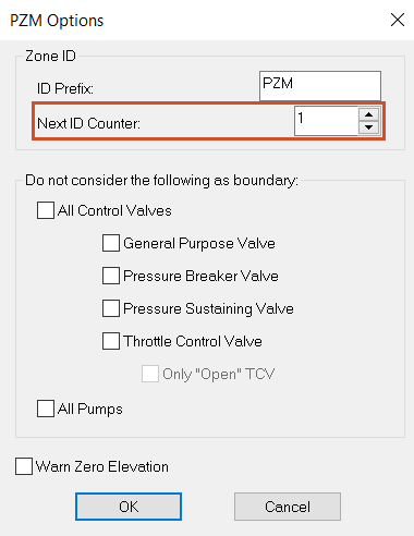
in the pressure zone manager, click options
00:52
in the PCM options, dialogue under zone id set, the next ID counter to one
01:00
This is because the PC M tool has been run prior to this exercise.
01:05
However, if you just started, you would start with PC M seven rather than PC M one.
01:11
So make sure you reset this any time you rerun the PZ M tool.
01:15
Click new to start the pressure zone wizard
01:19
on the first page next to store the elements, zone id in this field, enter zone
01:26
for output time. Enter zero hours.
01:32
for step one in the definition of trace area group,
01:35
select no user defined boundary pipes.
01:40
on the step two page.
01:41
You can define intra zone elements for the PC M to ignore them as zone delineates
01:46
but still treat them like junctions in the simulation.
01:51
in the new row, expand the type, drop down and set it to pump.
01:56
Then click select element
01:59
in the model zoom in and select pump P 100
02:04
pump P 100 is the north pump connected to W T P 100 that was included in PCM six.
02:10
In the original analysis,
02:12
you can also type in the pump id rather than manually selecting it from the map.
02:17
Click add row again and repeat these steps to add pump P 120 to a new row.
02:23
Now these pumps will be included in the closest pressure zone.
02:28
for step three, no boundary pipe elements are a user to find. So click next
02:34
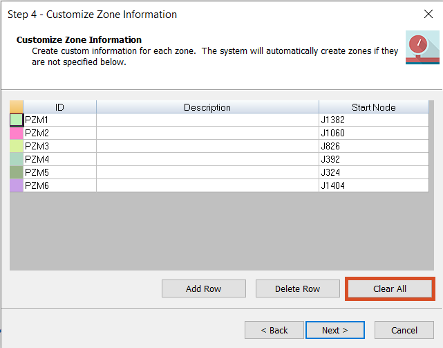
on the step four page,
02:35
you can see the customized zone information for the six
02:38
start nodes that was created during the earlier run.
02:41
Click clear all to remove this information and then click next
02:46
on the trace and analyze page. Click run
02:50
the PCM performs a trace analysis to identify pressure zones in the model.
02:54
With the updated information you provided,
02:57
you can see that five pressure zones are created
03:00
PCM. One to PCM five
03:03
PZ M six no longer exists and is now part of PZ three.
03:08
Click finish to close the wizard and return to the pressure zone manager
03:13
in the pressure zone manager.
03:15
Click the cell above the zone list to select all the zones and then click show zone,
03:21
move the pressure zone manager window to the side
03:23
and view the map with all pressure zones,
03:27
click close to exit the pressure zone manager.