00:03
To run a steady state analysis.
00:05
You must first set boundary conditions such as pump status or tank levels.
00:11
In this exercise, you define pump operations and assign an initial level to the tank
00:18
Double click the desired project dot APR X file to open
00:24
Once the project starts,
00:26
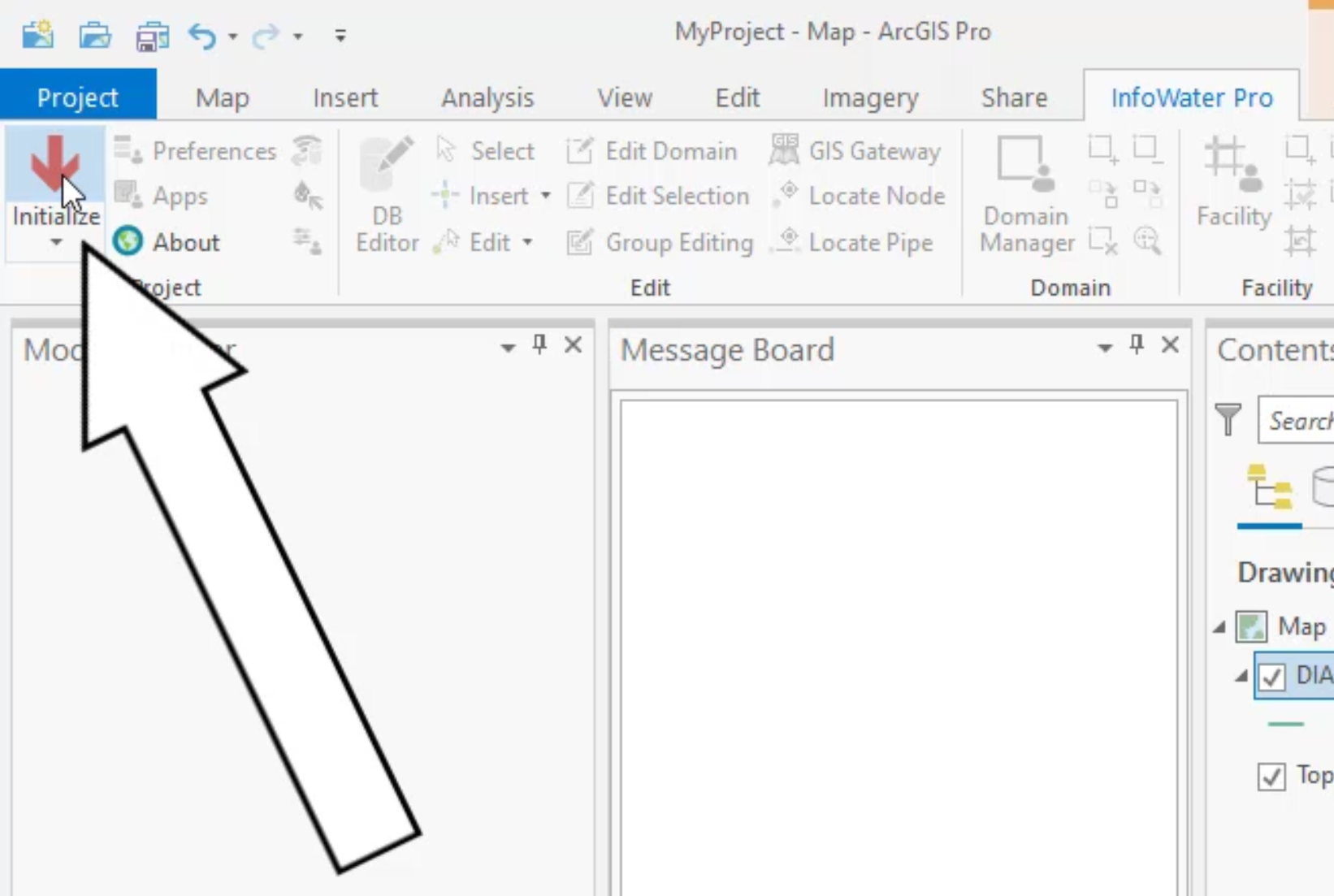
click the info water pro tab to open the info water Pro ribbon
00:30
in the project panel, click initialize
00:35
to start zoom to the north tank with an ID of T 5004
00:41
from the info water pro ribbon
00:43
edit panel, click the select tool, then select tank T 5004.
00:51
If you are having trouble finding this tank in the model,
00:54
you can use the model explorer to help locate it
00:58
in the attribute tab. Enter T 5004 in the name field,
01:04
and then click zoom to an active element
01:08
with tank T 5004 selected
01:10
from the model explorer
01:13
enter an initial level of 120.
01:17
This means that this tank will have a hydraulic grade line
01:20
or H G L of 120 ft above the ground.
01:23
Surface. During this static analysis,
01:30
locate in zoom to the south tank with an id of T 5000 and select it
01:37
in the attribute tab of the model explorer enter an initial level of 90.
01:44
This tank will have an HGL of 90 ft above the ground surface.
01:47
During this static analysis,
01:51
locate in zoom to the treatment plant with an ID of W T P 100
01:58
in the attribute tab of the model explorer. Enter ahead of 5880.
02:03
This treatment plant operates at a constant HGL of 5880 ft.
02:09
During this static analysis
02:12
now add pumps, P 100
02:14
P 120 to the domain which are the pumps located downstream of the reservoir.
02:21
On the info water pro ribbon in the domain panel, click the enlarged domain icon,
02:26
then select both pumps near the reservoir to add them to the domain.
02:31
The pumps and adjacent pipes will be selected,
02:35
click the reduced domain icon and then select the
02:38
adjacent pipes to remove them from the domain.
02:42
Only the pumps should remain
02:44
on the info water pro ribbon in the edit panel,
02:47
click group editing to open the group editor,
02:51
select pump slash valve status. Make sure that the initial status is set to close
02:59
when you are prompted to confirm click. OK. And then close. The group editor
03:05
on the info water pro ribbon
03:07
in the domain panel. Click the clear domain icon.
03:11
Now, the pumps and tank are ready for a steady state analysis.