00:03
To create an integrated model, the river and urban drainage networks need to be linked.
00:09
This can be done in 1D with conduits that spill from the urban drainage network into the river.
00:16
To complete this exercise, open the transportable database .icmt file for this tutorial.
00:24
In the transportable database window, right-click the top-level folder and select Copy.
00:31
In the popup, click Continue. In the Model Group window, right-click the Database and select Paste.
00:37
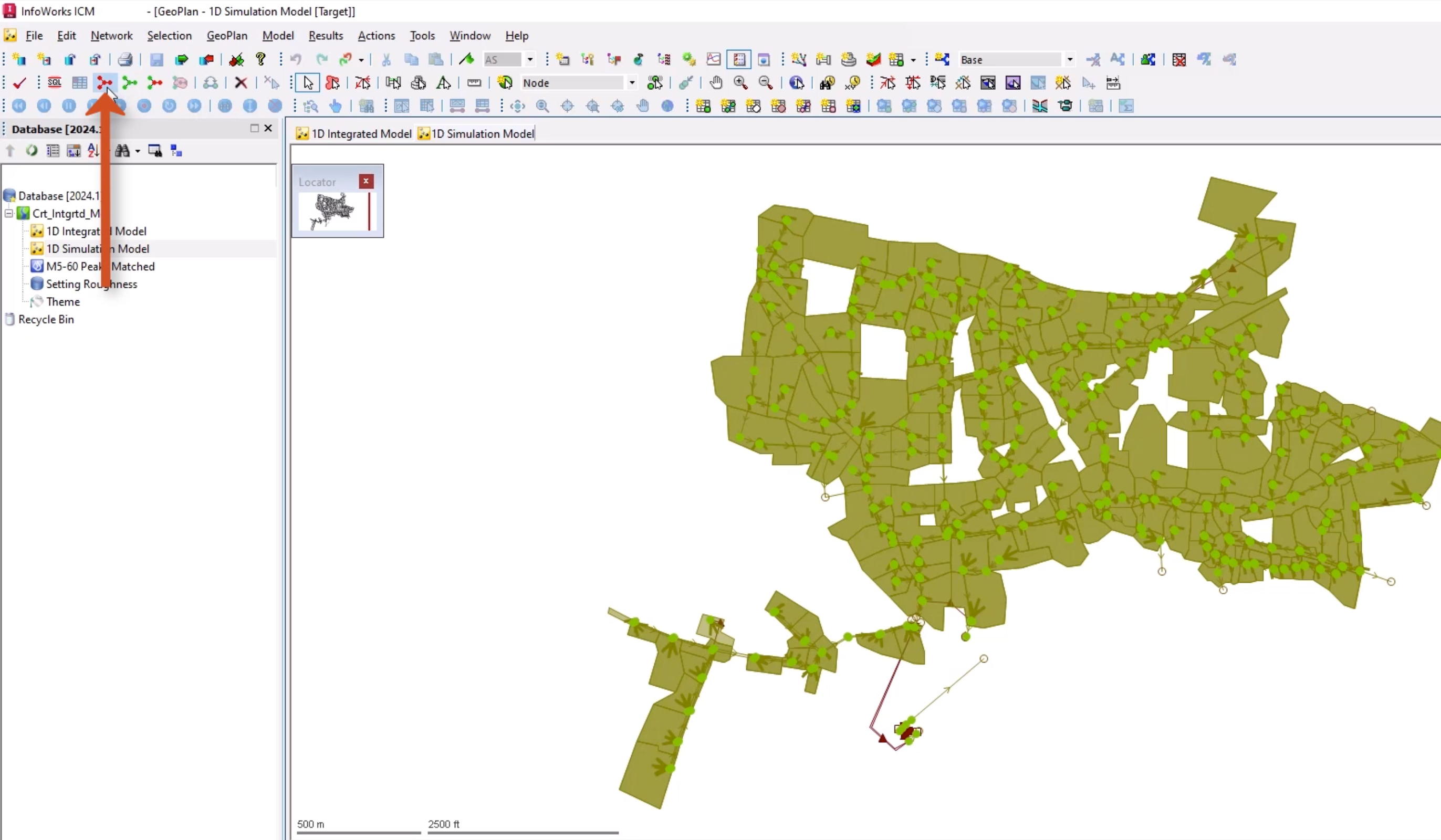
From the Database, double-click 1D Integrated Model to open the river model on the GeoPlan.
00:44
Double-click 1D Simulation Model to open the sewer model on the GeoPlan.
00:50
Ensure that you have the 1D Simulation Model window selected, and from the Selection toolbar, click Select all objects.
00:60
From the Edit menu, select Copy object(s).
01:04
Switch to the 1D Integrated Model window.
01:09
From the Edit menu, select Paste append object(s).
01:14
This pastes your urban drainage network into the new network.
01:19
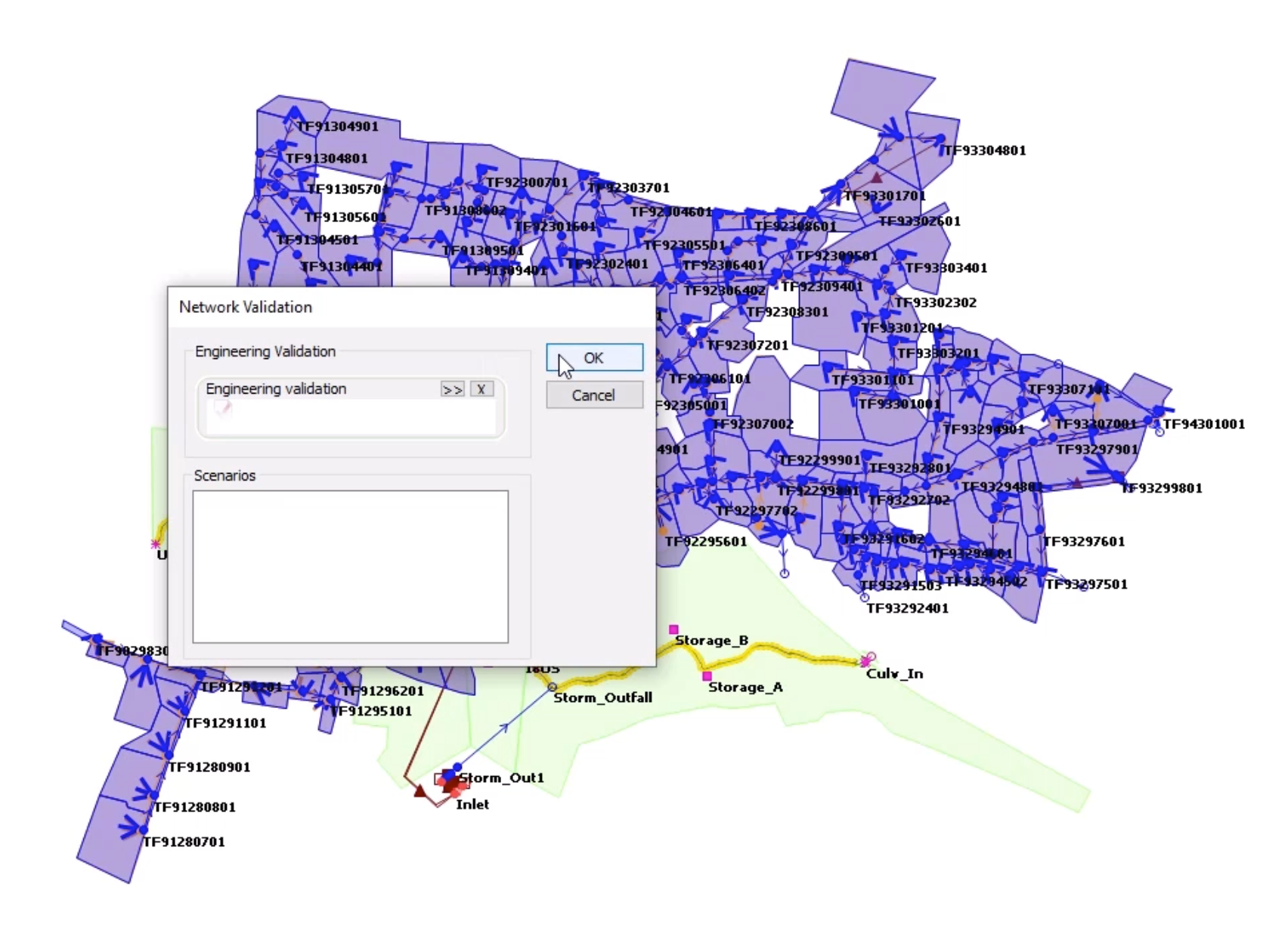
Click Validate to make sure there are no errors in your network, and then click OK.
01:25
Click Commit changes to database to save your changes.
01:30
Add a comment, such as “Copied across sewer model” Click OK.
01:36
At the moment, the river network and urban drainage network co-exist within the same model network.
01:43
However, there is nothing linking the two components of the model.
01:47
You can now couple the 1D components together.
01:51
It may be useful to adjust the properties and themes, as the GeoPlan may start to become cluttered.
01:58
Right-click the GeoPlan and select Properties & Themes.
02:03
On the Layers and Themes tab, in the Node row, enable AutoLabel.
02:09
In the rows for Subcatchments and Storage areas, disable Display.
02:21
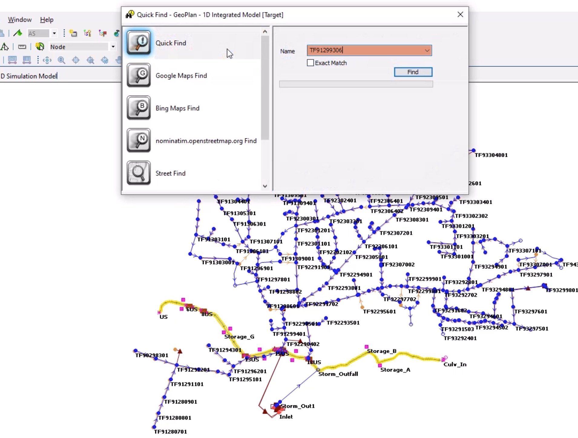
Click Find in GeoPlan and perform a Quick Find for TF91299306.
02:31
Once the node is located, close the Quick Find window.
02:35
There are three outfalls at this location.
02:39
Currently, flow is lost from the system at these points rather than being transferred to the river network.
02:46
You can connect the sewers to the river using the break nodes.
02:51
Double-click conduit TF91299304.1, which discharges to outfall TF21299305.
03:04
You can change the GeoPlan properties of the conduit locations, but you do not want ICM to adjust the physical properties.
03:13
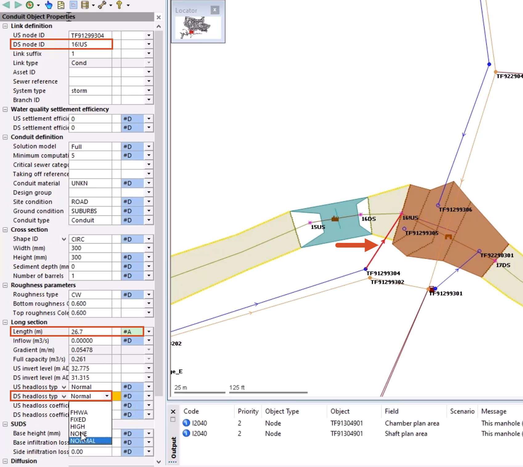
In the Properties window, for the Length field, use the drop-down to change the flag from the built-in #D to #A.
03:23
This prevents ICM from automatically updating the length.
03:28
If you need to add a user-defined flag, you can do so from the File menu,
03:34
by selecting Database settings > User defined flags.
03:39
In the Properties window, change the DS Node ID to 16!US using the drop-down list, or by manually entering the value.
03:52
This automatically moves the link.
03:55
An inline validation warning appears for the DS headloss type field, as it is no longer appropriate.
04:02
This is because it was developed for headloss at typical manholes.
04:07
Change the DS headloss type value from Normal to NONE.
04:12
Using this same process, connect the following links to the outfalls:
05:03
For the first two, remember to change the flag for the Length field, and set the DS headloss type to NONE.
05:10
The third link is a flap valve, so you just need to set the new DS node ID.
05:16
Often, it is necessary to add new break nodes into the network so that the sewers can be connected to the river.
05:24
It is best to plan for this during the original river build, but that is not always possible if models are inherited.
05:32
When you add a break node to split the river reach, it creates an interpolated section.
05:37
This is not always logical, and sometimes the geometry can become skewed.
05:43
When this occurs, the river reaches should be manually corrected and rebuilt.
05:49
Click Find in GeoPlan and perform a Quick Find for Storm_outfall.
05:56
Once the node is located, close the Quick Find window.
06:00
On the GeoPlan, double-click the outfall node to open the Properties window.
06:06
Change the Node type to Break.
06:09
Do not worry about the inline validation error that is created.
06:14
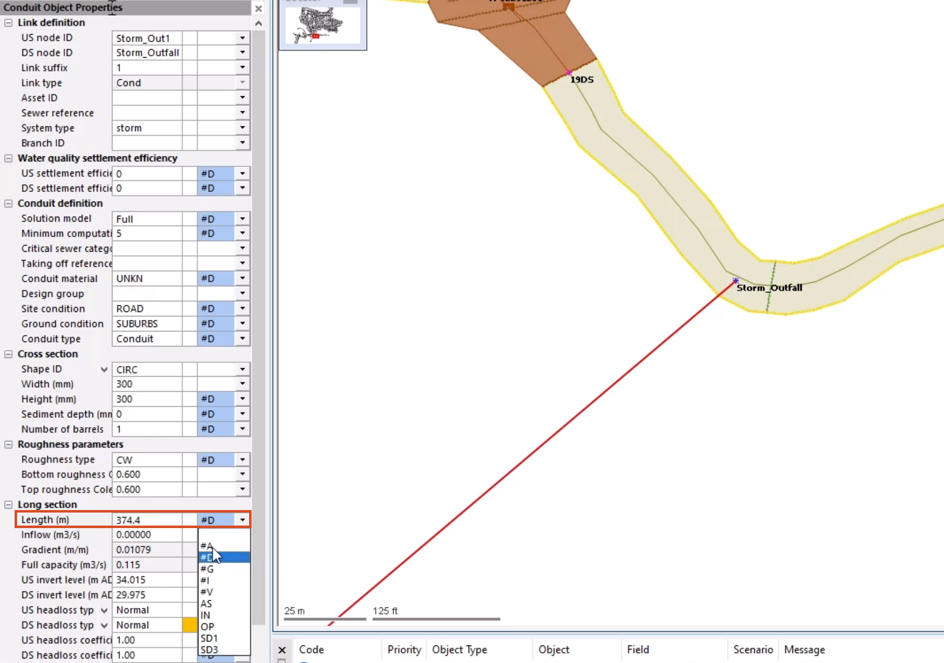
Double-click the incoming link object Conduit: Storm_Out1.1 to open the Properties window for it.
06:24
Once again, change the flag for the Length field to your user-defined flag, and set the DS headloss type to NONE.
06:32
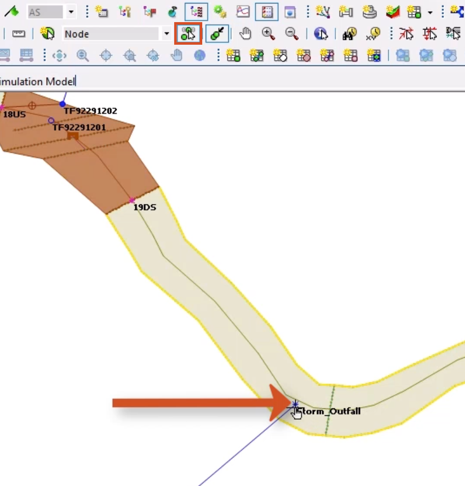
From the GeoPlan Tools toolbar, select Edit object geometry.
06:38
Select node Storm_outfall.
06:41
The node turns red to indicate that it is selected.
06:46
Drag the node over the river center line, and drop it in a location that you are sure intersects the line.
06:53
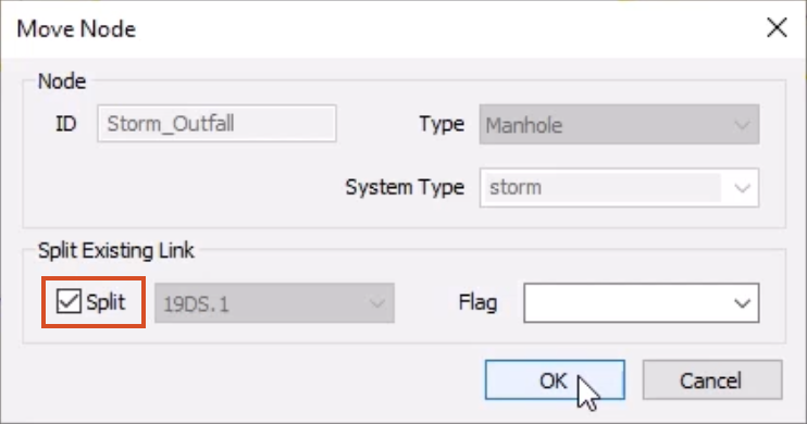
In the Move Node popup, in the Split Existing Link section, enable Split, and then click OK.
07:00
ICM generates a new interpolated cross section at the break node location, and the river reach is now split into two.
07:09
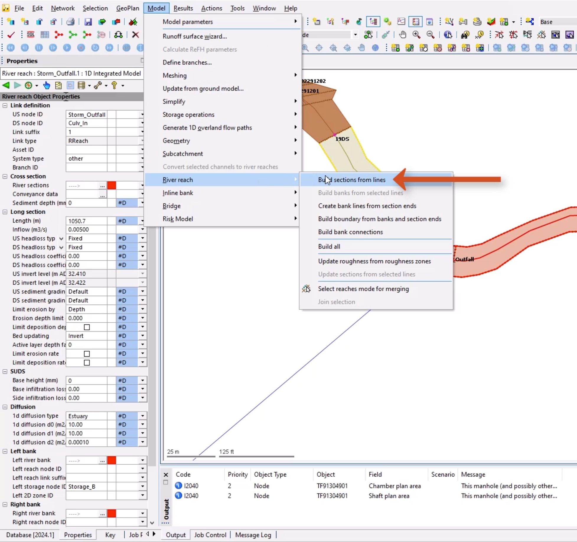
Double-click the river reaches on either side of your new cross section to check the Properties for validation warnings.
07:17
The upstream river reach looks good, but the downstream reach displays several inline validation warnings.
07:24
You can rebuild this river reach.
07:26
Make sure that river reach Storm_Outfall.1 is selected.
07:32
From the Model menu, select River reach, and then choose Build sections from lines.
07:40
Select OK to close the warning popup.
07:44
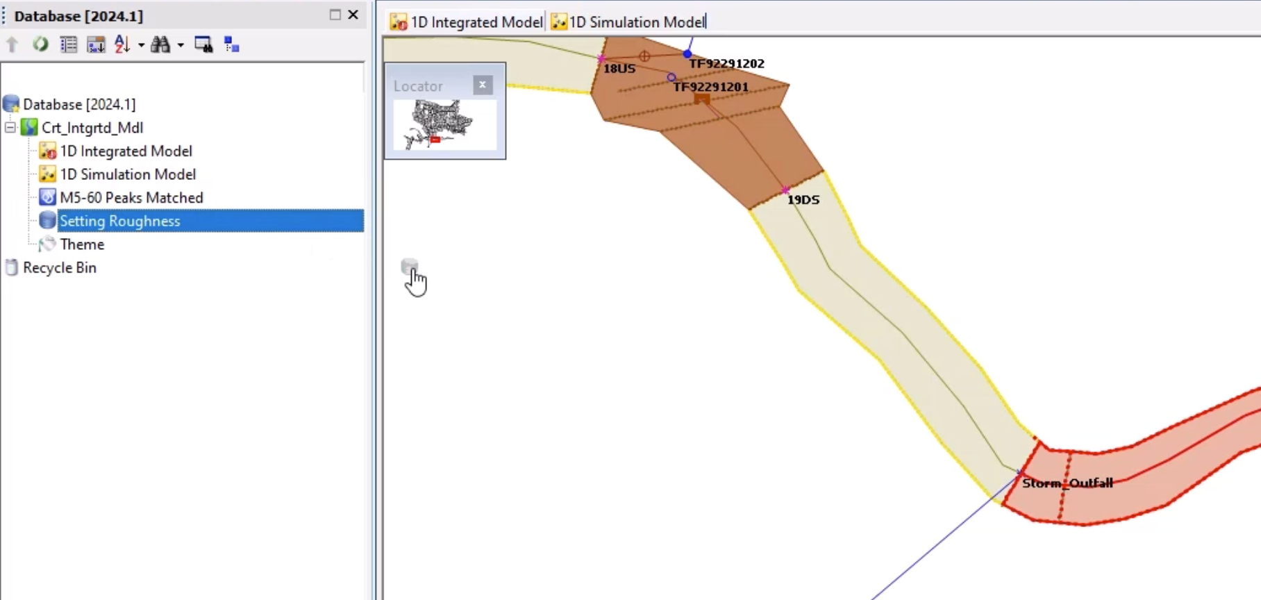
There is still one validation warning for the River sections field.
07:49
From the Database, drag the Setting Roughness SQL onto the GeoPlan.
07:56
This updates the missing roughness values.
07:60
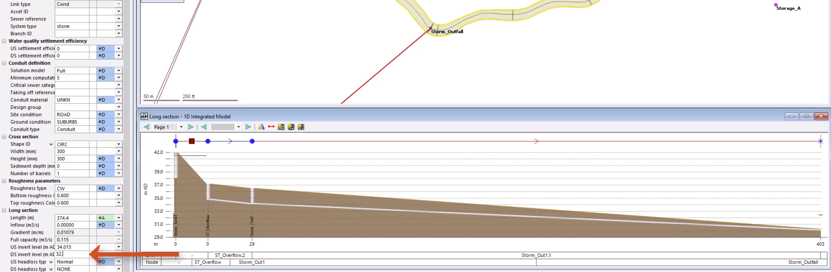
With the validation warnings corrected, you can check the downstream invert level of the conduit.
08:06
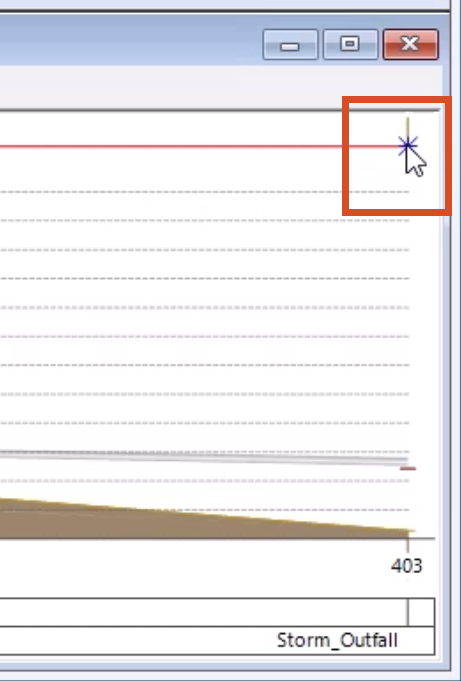
From the GeoPlan Tools toolbar, click the Long Section pick tool, and then click Storm_Out1.1.
08:16
Note that it is below the bed level of the river and must be corrected.
08:21
Outfall levels are often assumed where data is not available and can require correction.
08:27
In the Properties window for Storm_Out1.1, set the DS invert level (m AD) to 32.500.
08:38
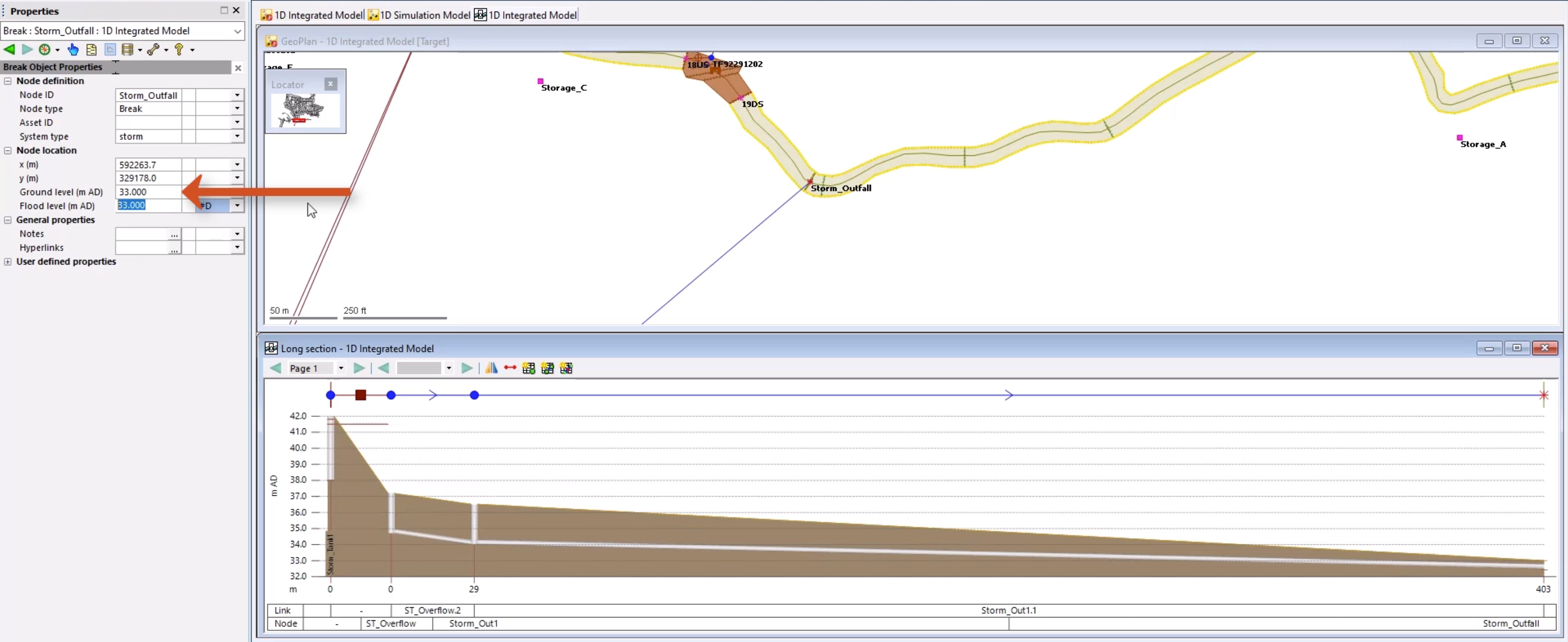
In the Properties window for Storm_Outfall, set the Node ground level to 33.000 m AD.
08:48
Click Validate to make sure there are no errors in your network.
08:53
Click Commit changes to database to save your changes.
08:57
Add a comment, such as “Connected outfall locations into the river reaches”.
09:06
The two networks are now connected as an integrated model.
09:10
Flow can now transfer between the urban drainage network and the river channel via the connection points that you created.