00:04
A 2D zone does not go through the same initialization process as a 1D model
00:09
and there is no connection between the 1D and 2D engines during initialization.
00:16
Therefore, it is necessary to specify initial conditions within the 2D zone
00:22
to prevent surges of water occurring when the simulation starts.
00:27
The Initial Conditions 2D object is used to assign initial hydraulic, infiltration, and water quality values
00:37
to 2D mesh elements at the start of a 2D simulation.
00:41
These initial conditions can be applied to the entire 2d zone or individual areas using initial condition zones.
00:51
Open the transportable database .icmt file for this tutorial.
00:57
In the transportable database window, right-click the top-level folder, and select Copy.
01:04
In the popup, click Continue.
01:08
Right-click the Database and select Paste (with children).
01:11
In the Copying pop-up, enable Copy ground models.
01:18
Open 1D/2D River Model on the GeoPlan.
01:24
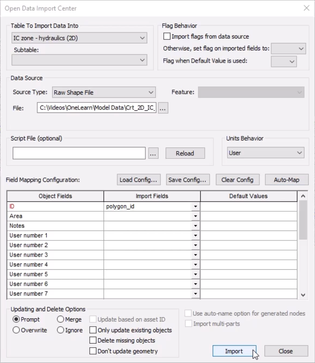
From the Network menu, click Import > Open Data Import Centre to open the ODIC.
01:32
In the Table To Import Data Into drop-down, select IC zone - hydraulics (2D).
01:41
Under Data Source, ensure that the Source Type is set to Raw Shape File.
01:47
Click the More (…) button, navigate to the files for this tutorial,
01:54
select IC zone – hydraulics (2D).shp, and then click Open.
02:02
In the Field Mapping Configuration section, click Auto-Map to search the import file for fields that match those
02:11
that define the nodes in the network.
02:14
Click Import, and then OK to close the notification.
02:22
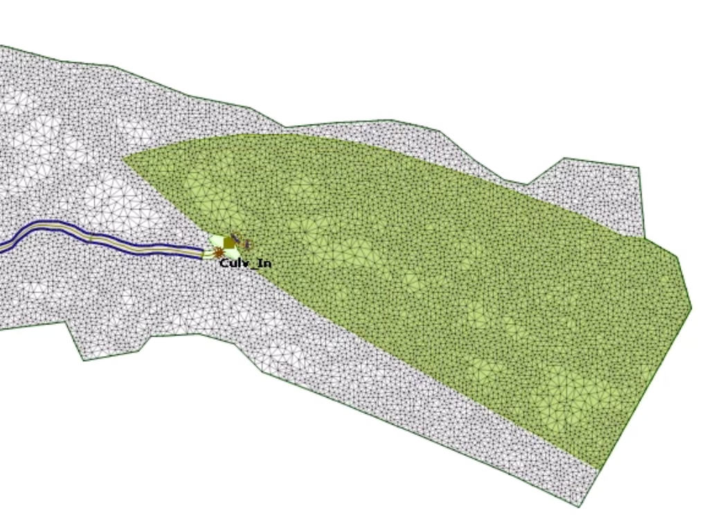
The IC Zone is imported into the model as a polygon.
02:27
This area covers the extent of where the initial conditions are to be applied.
02:33
Now the initial condition objects must be created.
02:37
For simplicity these will be imported from existing files.
02:41
In the Database, right-click the Model Group, and select Import InfoWorks > Initial conditions 2D > from InfoWorks format CSV file.
02:53
Navigate to the folder location where you downloaded the exercise files.
02:58
Select the Initial conditions 2D.csv file, and then click Open.
03:06
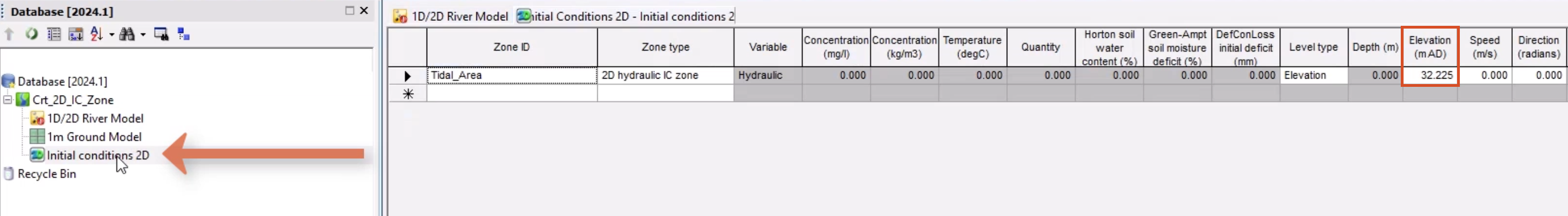
Double-click the object to inspect the content.
03:10
This will apply a level of 32.255mAD to the Tidal_Area IC zone.
03:18
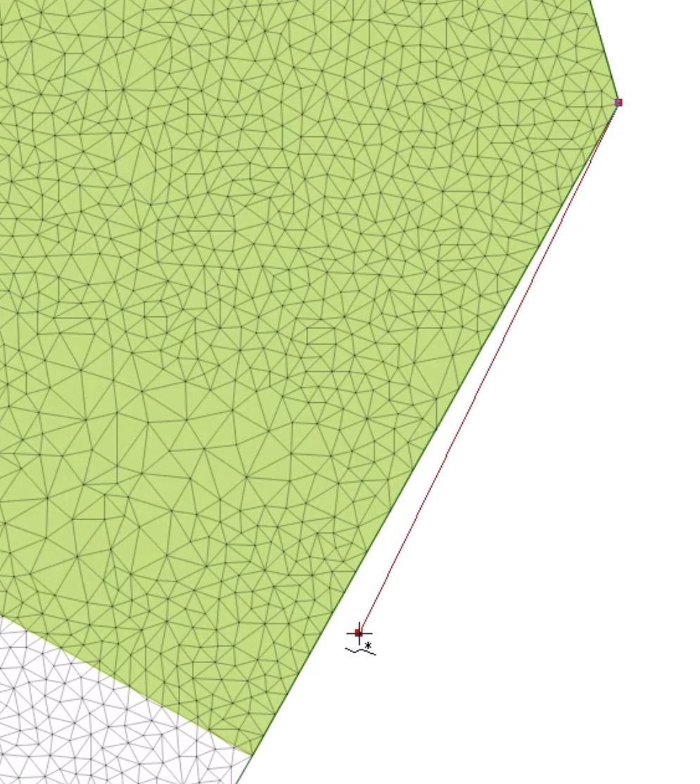
You can apply a level file at the boundary line of the IC zone to set the tide level during a simulation.
03:26
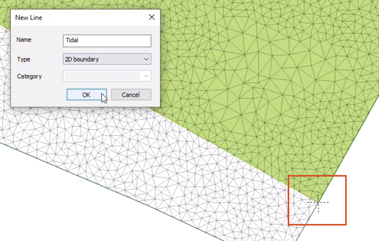
From the GeoPlan Tools toolbar, expand the New Object Type combo box and select Line.
03:36
Click New Object and at the downstream extent of the IC zone, add a line.
03:42
Make sure that the line is collinear with the boundary of the IC zone.
03:48
Double-click to close the line.
03:51
In the New Line popup, add a Name of “Tidal”, and then set the Type to 2D boundary.
04:02
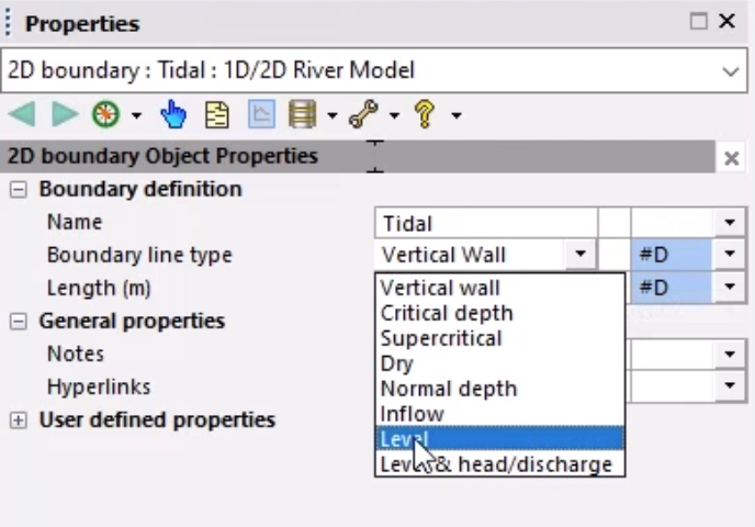
The 2D Boundary Properties window opens.
04:05
Set the Boundary line type to Level.
04:09
This will allow you to set the level at the boundary via a Level Event.
04:16
Regenerate the mesh so that these additional objects are included.
04:21
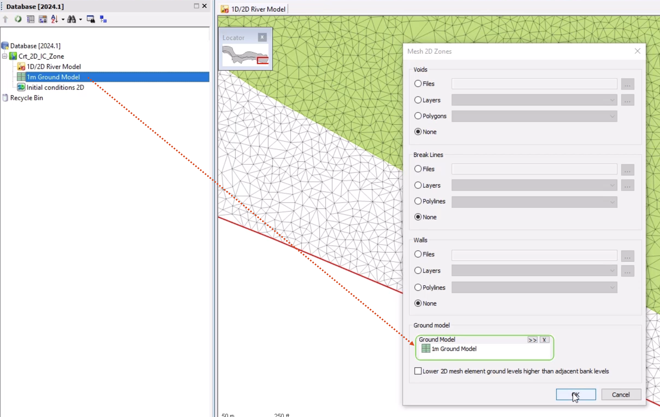
With the 2D zone selected on the GeoPlan, select Model > Meshing > Mesh 2D zones.
04:29
From the Database, drag the 1m Ground Model into the Mesh 2D Zones dialog
04:36
and drop it into the Ground Model group box and then click OK.
04:42
In the Schedule Job(s) dialog, click OK.
04:47
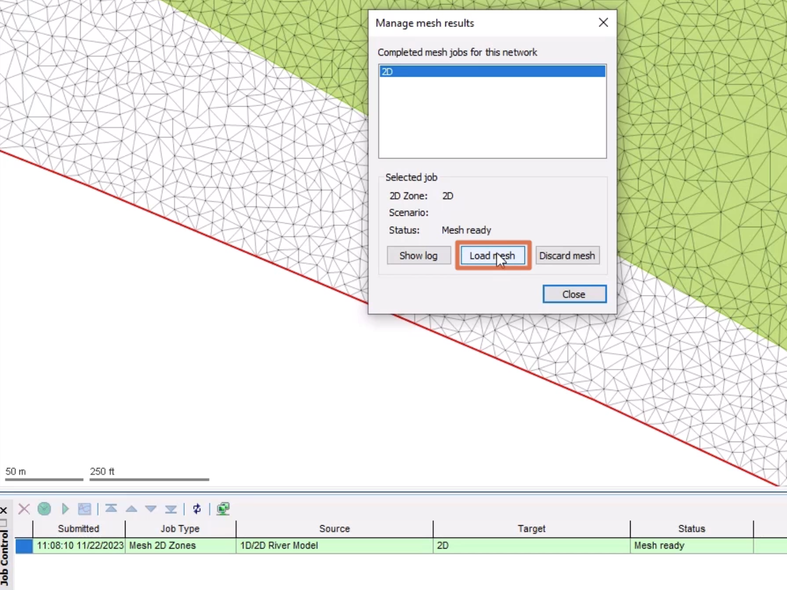
Once the mesh has completed, from the Job control window,
04:52
click the Mesh ready status to open the Manage mesh results window.
04:58
Click Load mesh, and then Close.
05:02
Click Validate to make sure there are no errors in your network, and then click OK.
05:08
Click Commit changes to database to save your changes.
05:13
Add a comment, such as "Added IC Zone and 2D boundary".
05:22
The 1D-2D river model is now complete and can be used for simulations.