00:04
In ICM, coupling at bank lines connects 1D model objects to multiple 2D element faces.
00:11
This can occur at either river reach banks or inline bank links,
00:16
both of which are built from bank line data.
00:19
In this tutorial, you create bank lines for river reach objects and build a bank connection.
00:26
To begin, from the File menu, select Open > Open transportable database.
00:33
Navigate to the folder where you downloaded the exercise files for this tutorial,
00:39
select the .icmt file, and then click Open.
00:44
If you see a popup about opening the database as read-only, click Yes.
00:50
In the transportable database window, right-click the top-level folder, and select Copy.
00:57
In the popup, click Continue.
01:00
Right-click the Database and select Paste (with children).
01:05
In the Copying pop-up, enable Copy ground models.
01:12
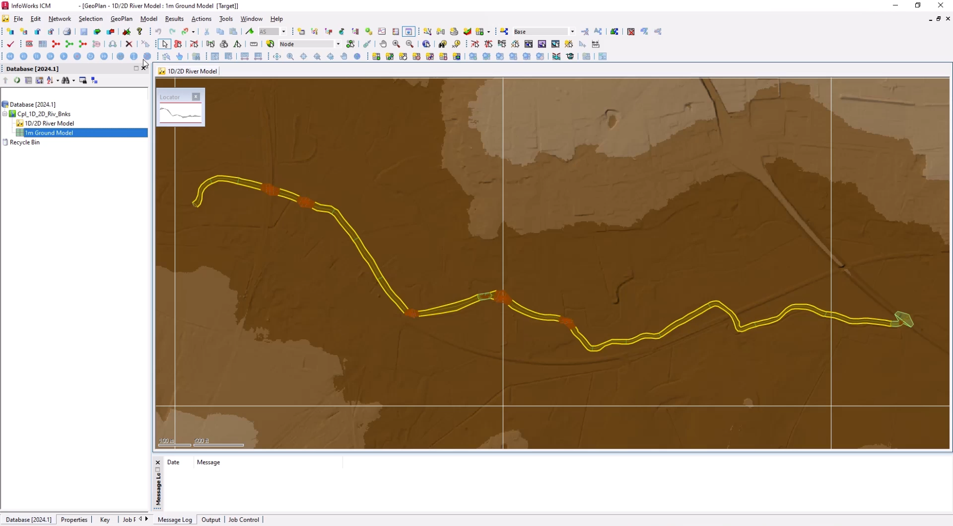
In the Explorer window, double-click 1D/2D River Model to open it on the GeoPlan.
01:21
From the Database, drag 1m Ground Model and drop it onto the GeoPlan.
01:28
You can now import a 2D zone.
01:31
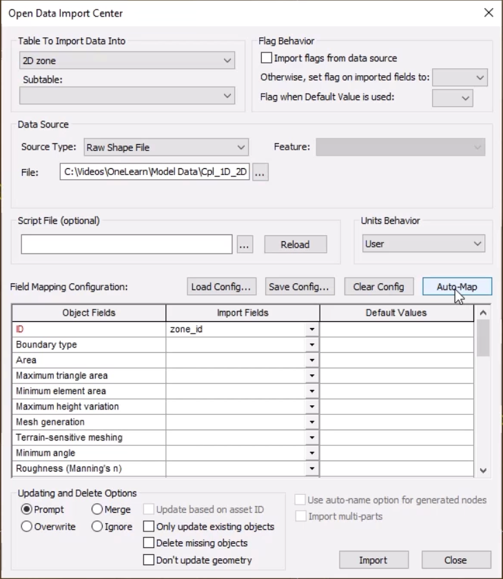
From the Network menu, click Import, then select Open Data Import Centre to open the ODIC.
01:40
In the Table To Import Data Into drop-down, select 2D zone.
01:46
Under Data Source, ensure the Source Type is set to Raw Shape File.
01:53
Click the More (…) button, navigate to the exercise files for this tutorial,
01:59
select 2D Zone.shp, and then click Open.
02:05
In the Field Mapping Configuration section,
02:08
click Auto-Map to search the import file for fields that match those defined in the network.
02:17
An import notification lets you know how many objects were imported.
02:22
Click OK, and then Close the ODIC.
02:26
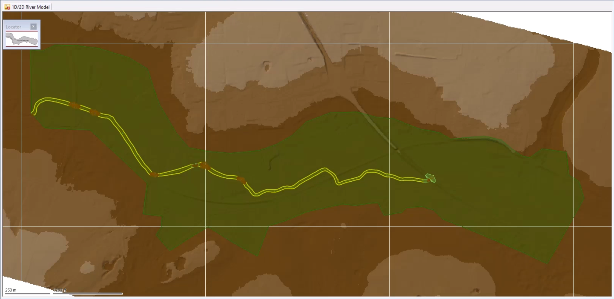
The 2D zone is imported into the model and is displayed as a green polygon.
02:33
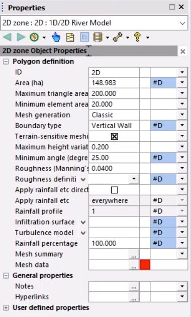
Click the Select tool, and then double-click the 2D zone to open its Properties window.
02:40
Set the following mesh parameters:
02:43
Set the Maximum triangle area to 200
02:47
Set the Minimum element area to 20
02:51
Set the Mesh generation to Classic
02:55
Enable Terrain-sensitive meshing
02:58
Set the Maximum height variation to 0.2
03:03
Set the Roughness (Manning's n) to 0.04
03:09
With these changes made, you can generate the mesh.
03:13
Make sure the 2D Zone is still selected on the GeoPlan.
03:18
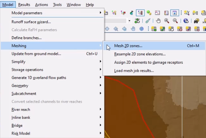
From the Model menu, select Meshing > Mesh 2D zones.
03:23
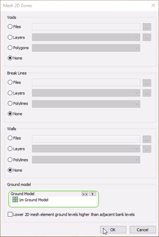
From the Database, drag the 1m Ground Model into the Mesh 2D Zones dialog
03:30
and drop it into the Ground Model group box.
03:34
Click OK to mesh the 2D zone.
03:38
In the Schedule Job(s) dialog, click OK.
03:43
From the Window menu, select Job control window to display the status of the mesh job.
03:50
Once the mesh is complete, it can be loaded into the model.
03:54
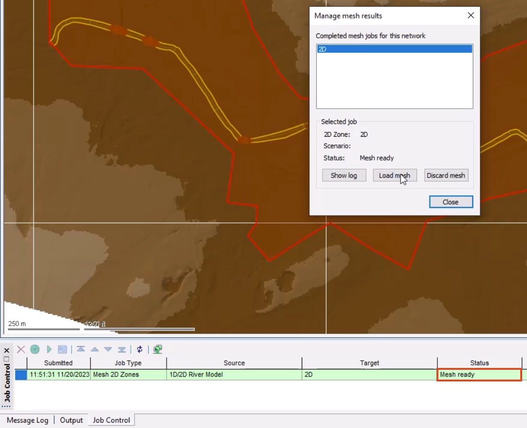
From the Job control window, click the Mesh ready status
03:58
to open the Manage mesh results window.
04:02
Click Load mesh, and then Close.
04:06
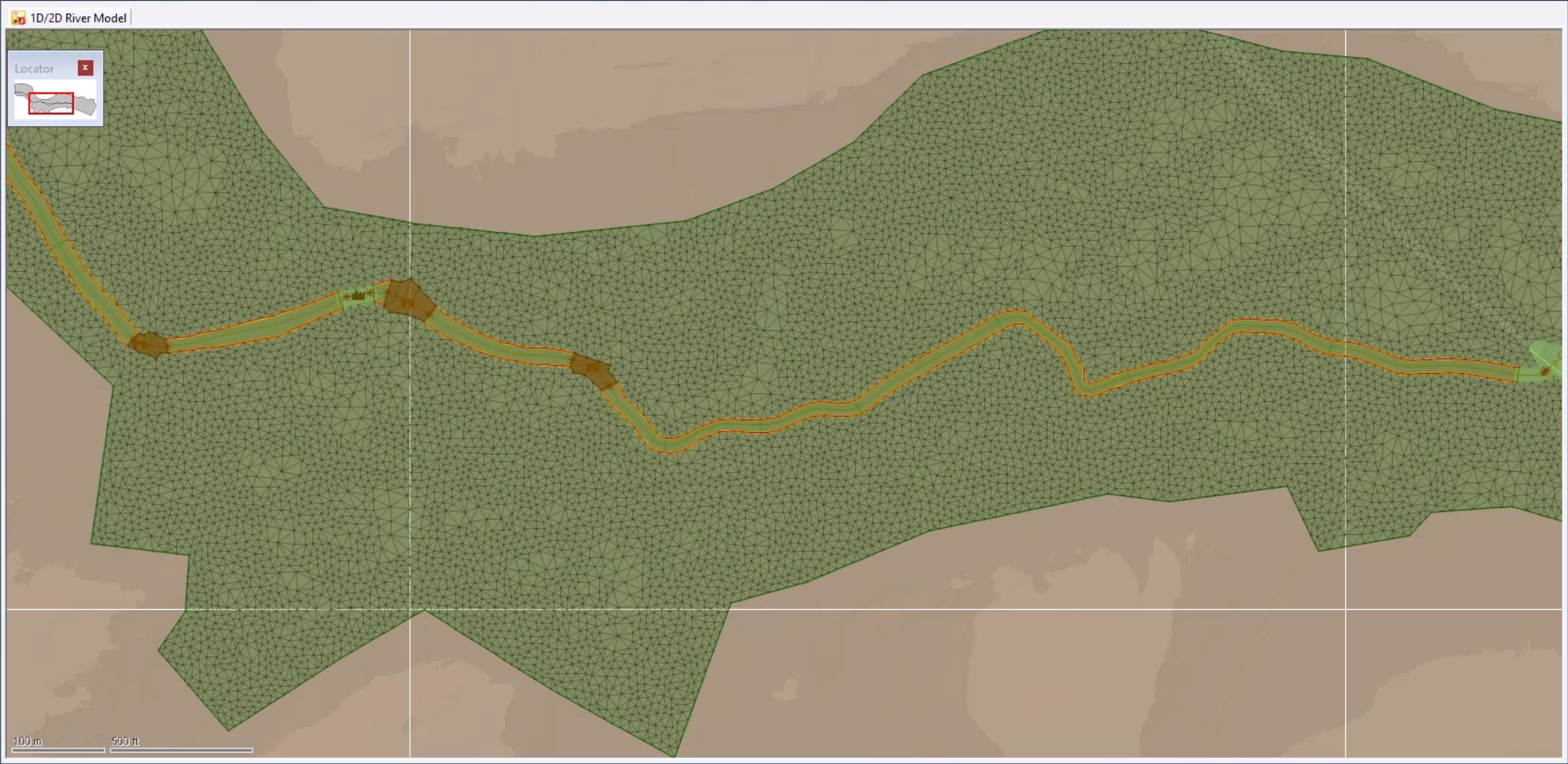
Inspect the 2D mesh to see how the terrain sensitive meshing has affected the element sizes in different areas of the model.
04:14
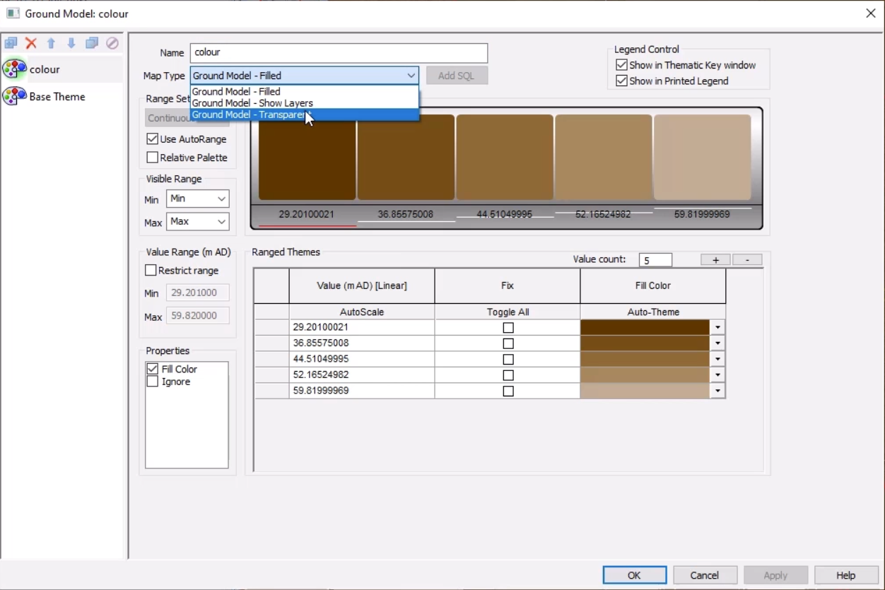
It may be helpful to adjust the Ground Model theme to see the mesh better.
04:20
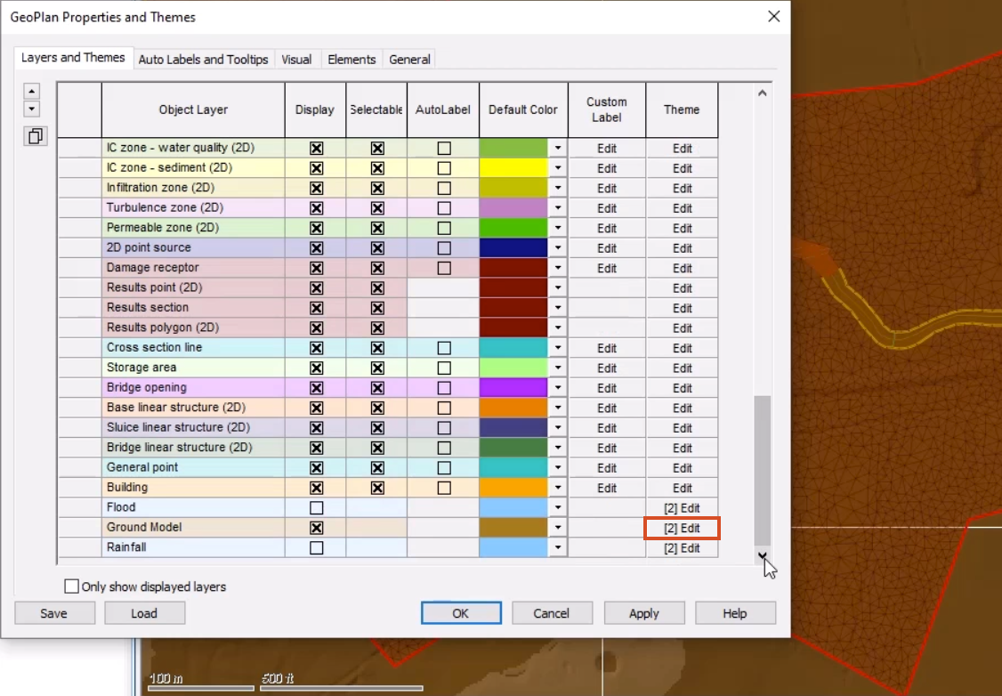
Right-click the GeoPlan and select Properties & themes.
04:25
On the Layers and Themes tab, for the Ground Model object layer, in the Theme column, click Edit.
04:33
In the Map Type drop-down, select Ground Model – Transparent.
04:38
Click OK, then OK again to close the GeoPlan Properties and Themes window.
04:45
Notice that the 2D zone extends beyond the river model.
04:50
This is because this downstream area is complex and best represented in 2D.
04:56
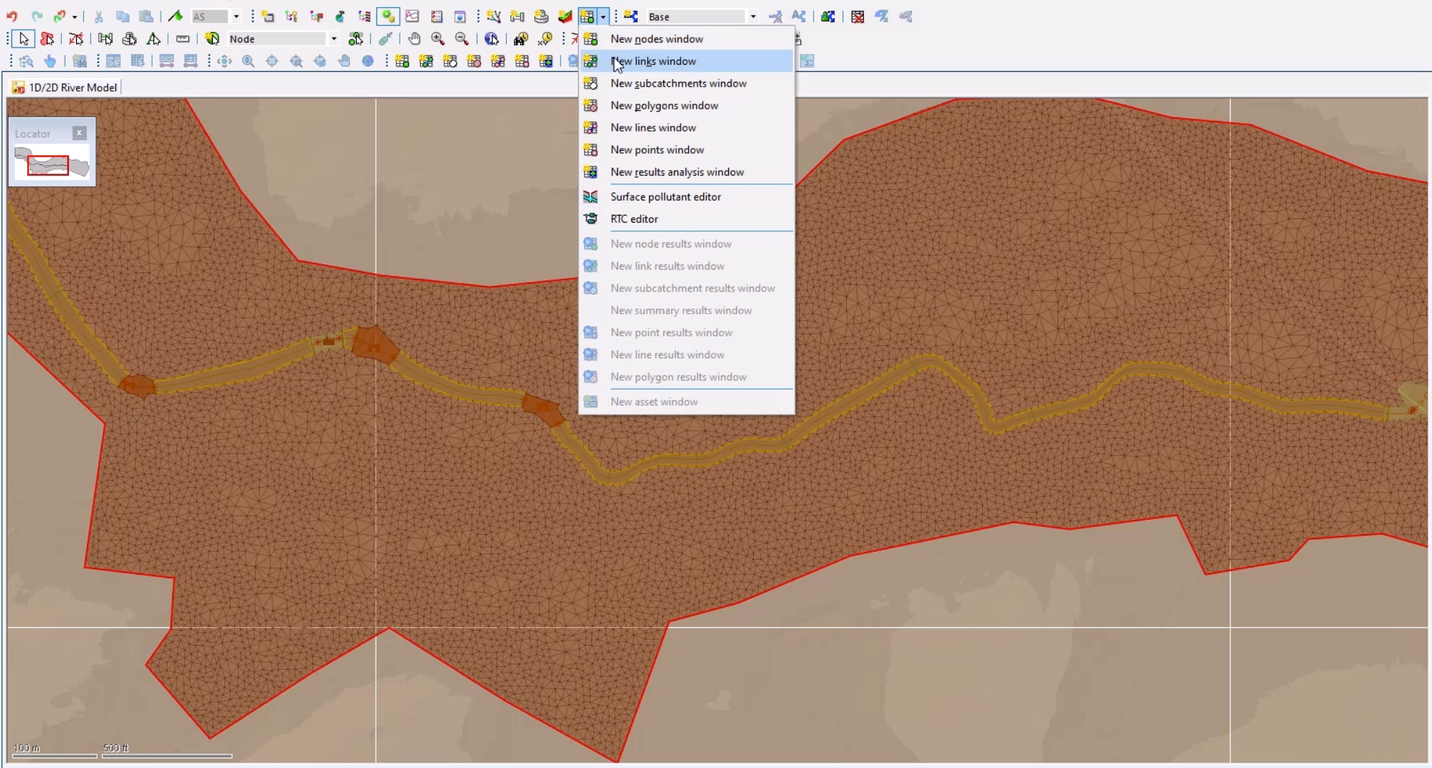
From the Windows toolbar, expand the Grid windows drop-down and select New links window.
05:04
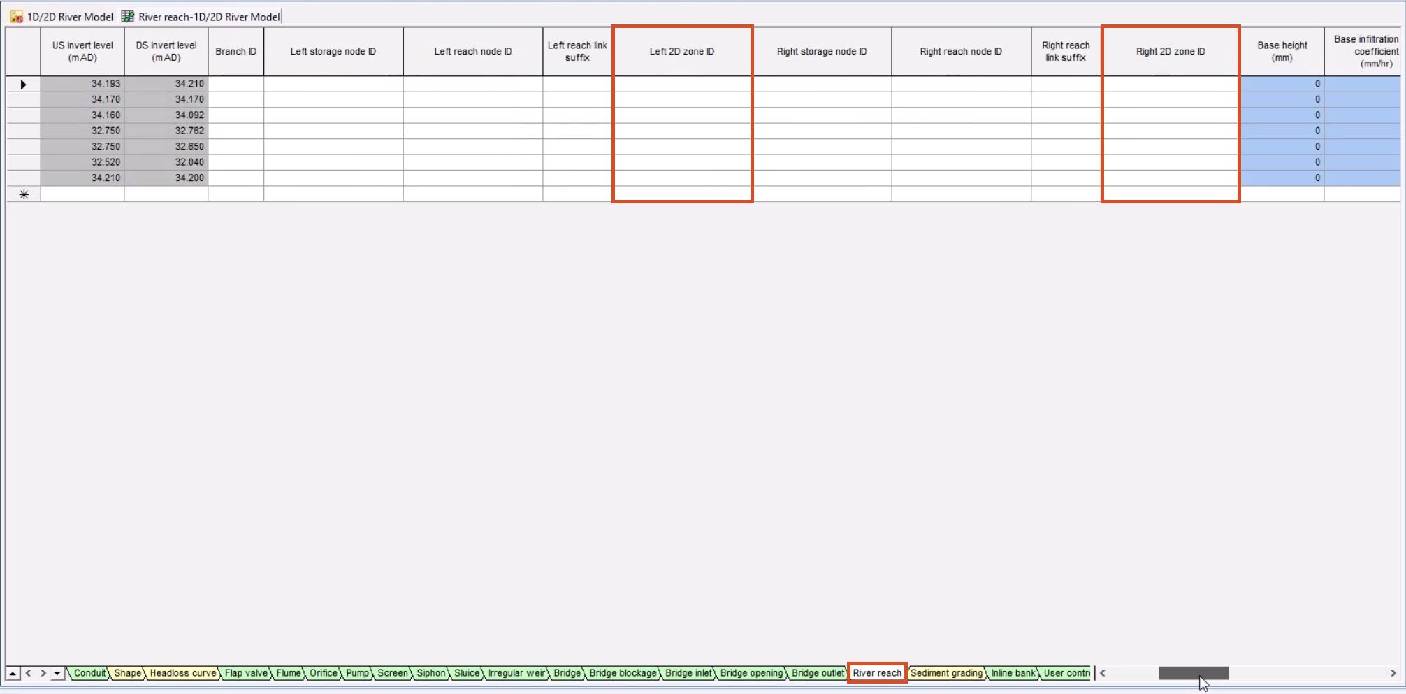
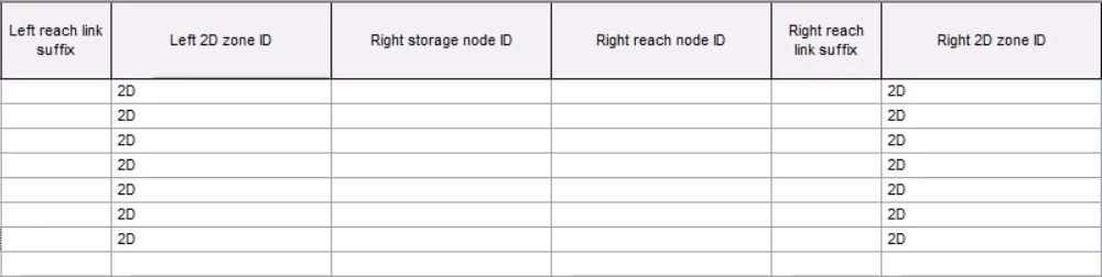
At the bottom of the grid window, select the River reach tab to view data for the seven river reaches.
05:11
Note that the Left 2D zone ID and Right 2D zone ID columns are blank.
05:19
Currently, if you ran a simulation on the model, there would be no exchange of flow.
05:25
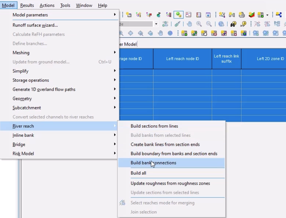
To connect the bank lines to the 2D zone, click the top left of the grid to select all the river reaches.
05:33
From the Model menu, select River reach > Build bank connections.
05:39
The Left 2D zone ID and Right 2D zone ID columns now display “2D”, the name of the 2D zone you imported earlier.
05:50
Close the grid window.
05:52
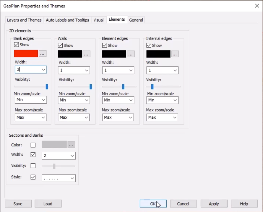
To help visualize the bank lines in the model, right-click the model on the GeoPlan and select Properties & themes.
06:01
On the Elements tab, in the 2D elements section for Bank edges,
06:07
click More (…) to change the color to red, and then set the Width to 3.
06:17
At this point there are no bank connections, as you need to regenerate the mesh.
06:23
With the 2D zone selected on the GeoPlan, select Model > Meshing > Mesh 2D zones, and then click OK.
06:33
In the Schedule Job(s) dialog, click OK.
06:38
Once the mesh is complete, from the Job control window,
06:43
click the Mesh ready status to open the Manage mesh results window.
06:48
As you click Load mesh, note that the bank lines are correctly connected to the 2D zone,
06:55
highlighted by the red bank edges.
07:00
Click Validate to make sure there are no errors in your network, and then click OK.
07:07
Click Commit changes to database to save your changes.
07:12
Add a comment, such as "Added 2D zone and connected the banks".
07:21
You now have a 1D-2D river network that is coupled along the banks.