00:03
To generate a 2D mesh, you must first define the 2D zone and 2D boundaries.
00:11
The 2D boundary is primarily defined by the boundary edge of the 2D zone.
00:16
However, if you want to set different conditions for flow to exit under, or to bring flow into, the 2D zone,
00:25
you can use 2D boundary objects to define alternative boundary conditions.
00:30
The conditions of the object—porous wall, porous polygon, base linear structure,
00:37
or 2D boundary co-linear with the boundary of the 2D zone—override the 2D zone boundary type
00:44
where the boundary line and polygon boundary coincide.
00:48
To pass validation, the 2D boundary must be fully co-linear with the boundary of a 2D zone.
00:56
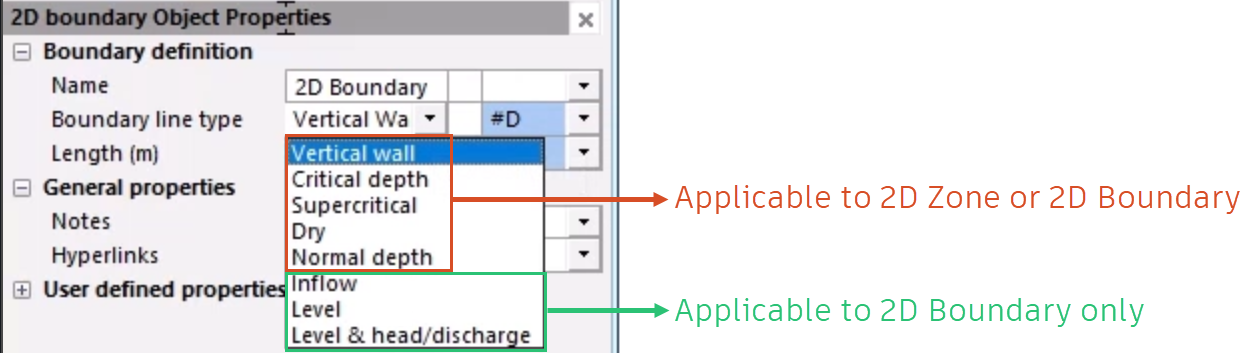
All of the 2D zone boundary types are available for 2D boundaries.
01:01
In addition, a boundary type of Inflow, Level, or Level & head/discharge can be assigned to a 2D boundary.
01:10
For a Vertical wall, the boundary line is considered to be an impermeable infinitely high barrier.
01:18
Similarly, in the case of a porous wall, porous polygon,
01:21
or base linear structure, coincident portions of the wall/polygon are considered infinitely high, regardless of any crest level specified.
01:33
For a Dry condition, the boundary line is considered to be bordered by a bottomless pit.
01:39
For the Normal Depth condition, it is assumed that slope balances friction forces (normal flow).
01:46
Depth and velocity are kept constant when water reaches the boundary, so water can flow out without energy losses.
01:54
To begin, from the File menu, select Open > Open transportable database.
02:01
Navigate to the folder where you downloaded the exercise files for this tutorial, select Def_2d_Zns_Bndr.icmt, and then click Open.
02:19
If you see a popup about opening the database as read-only, click Yes.
02:25
In the Explorer window that opens, right-click the top-level folder and select Copy.
02:32
In the popup, click Continue. Right-click the Database and select Paste.
02:36
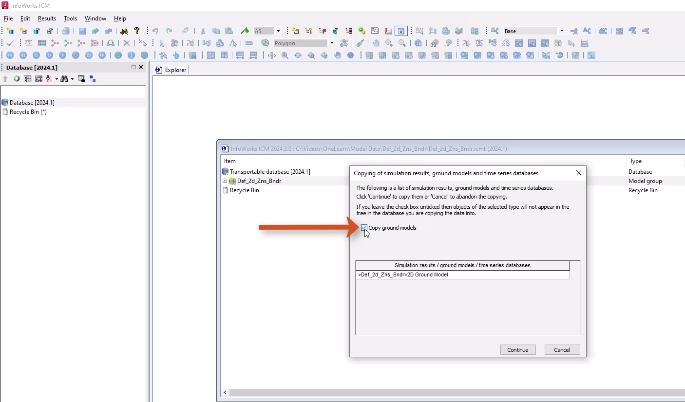
In the Copying popup, enable Copy ground models, and then click Continue.
02:43
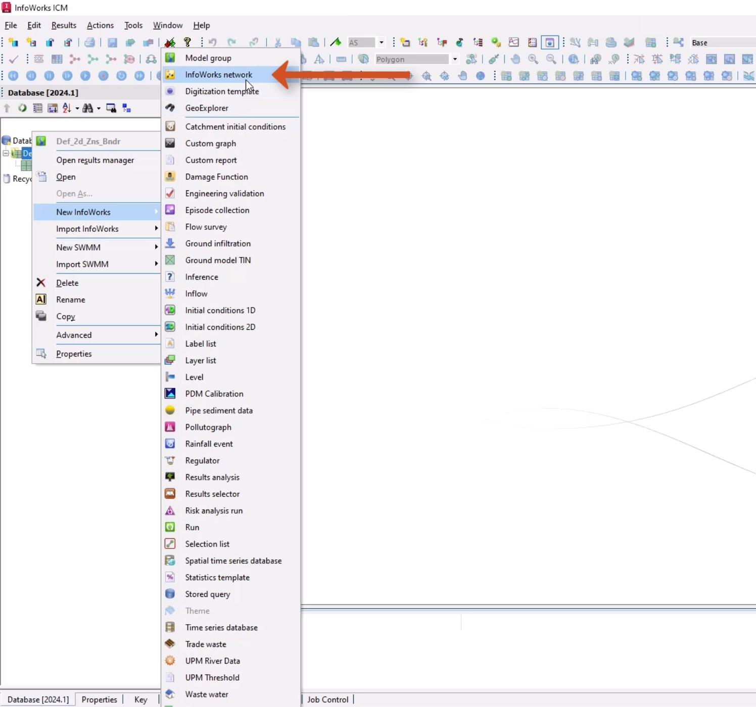
In the Database, right-click this new model group and select New InfoWorks > InfoWorks Network.
02:51
Add a name of “2D River Model”, and then click OK.
02:56
Double-click 2D River Model to open the blank network on the GeoPlan.
03:01
Drag the 2D Ground Model and drop it onto the open network.
03:06
Then, right-click the GeoPlan and select Zoom to ground model.
03:12
Here, you can see the bed level in the center with very steep sides.
03:16
This tutorial is simulating flow travelling from the bottom left to the top right.
03:23
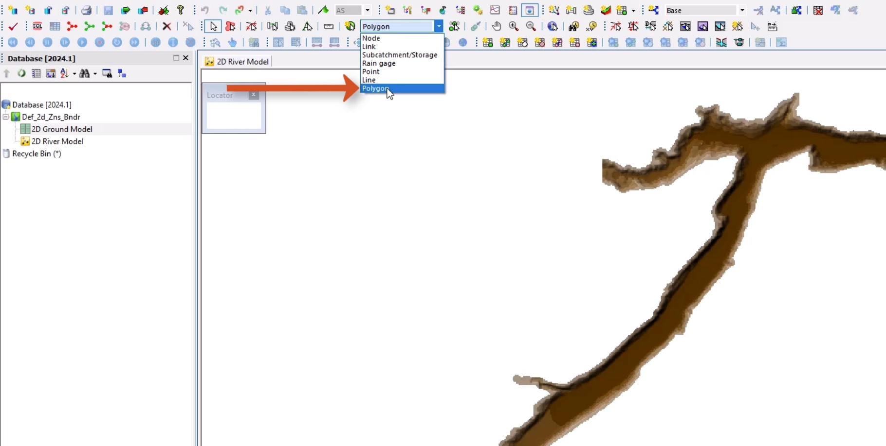
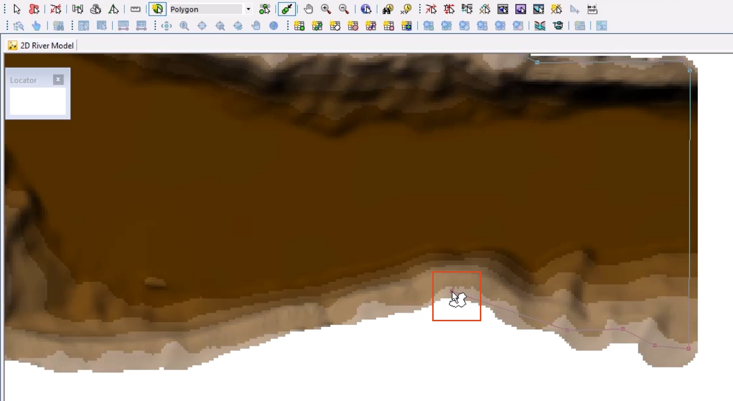
To define the 2D zone for mesh generation, from the GeoPlan Tools toolbar,
03:29
expand the New Object Type drop-down and select Polygon.
03:34
Now digitize a 2D zone polygon within the confines of the ground model by plotting vertices along its edge.
03:43
For this tutorial, there is no need to make the digitization overly detailed,
03:48
but you must ensure that all of the polygon is within the ground model, or an error will be generated during meshing.
03:57
Double-click to close the polygon.
04:01
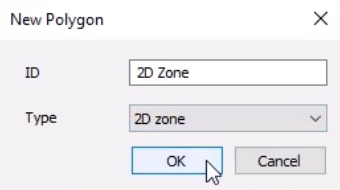
In the New Polygon popup, set both the ID and Type to 2D Zone.
04:11
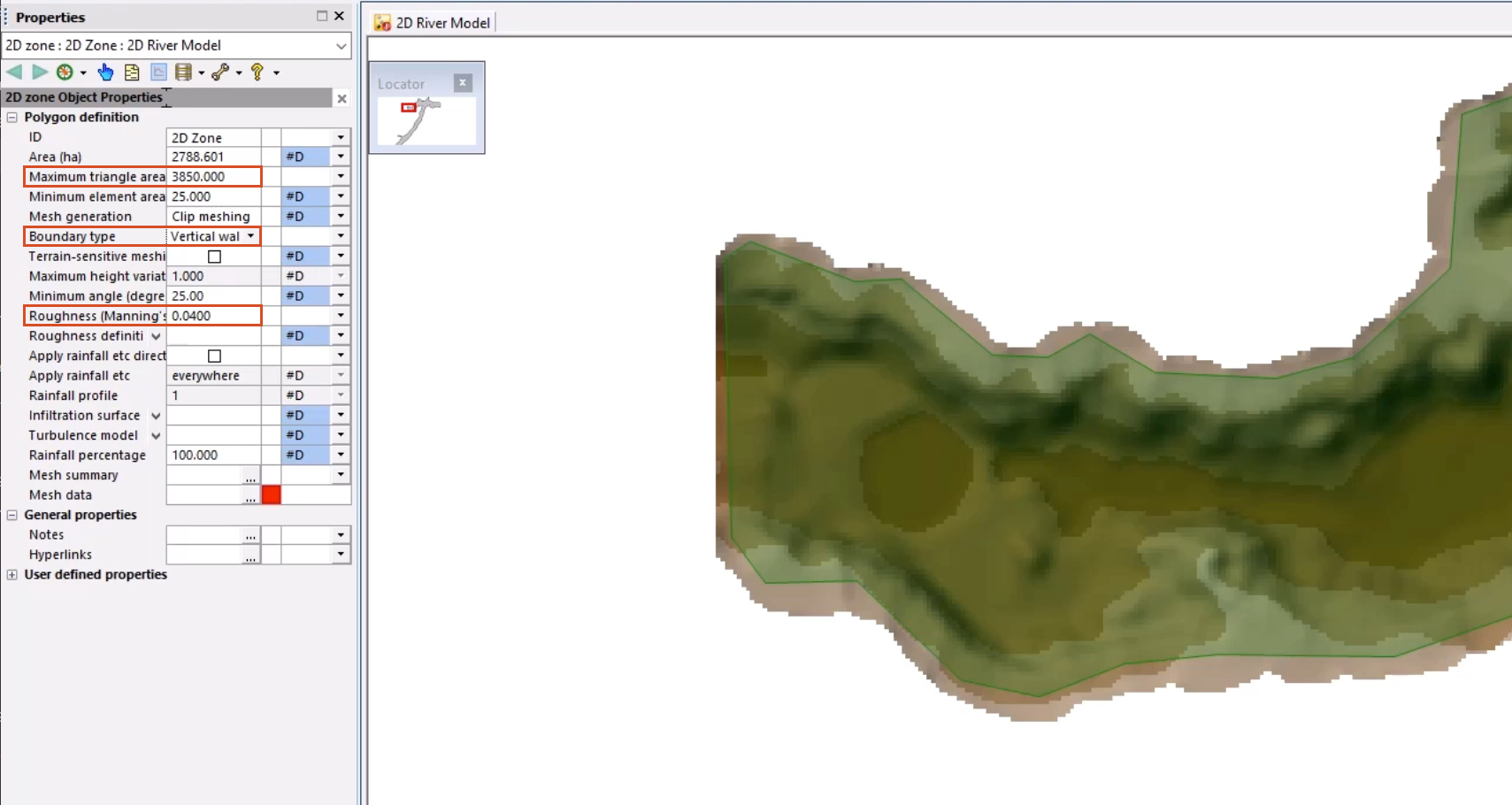
The 2D Zone Properties window appears, where you can make a few adjustments.
04:17
Change the Maximum Triangle Area to 3850 m2 and the Roughness (Manning’s n) to 0.04.
04:28
This provides the parameters for the 2D Zone from which the 2D mesh is created.
04:35
You can also set the Boundary Type, which defines how flow is allowed out of the 2D zone.
04:41
Here, it is set to Vertical Wall, so that any water reaching the edge acts as if it is hitting an infinite wall.
04:49
In the Mesh Data field, there is an inline validation error that will be rectified once you generate the mesh.
04:57
Next, define an alternative boundary—in this case, a 2D boundary line—to assign an inflow point.
05:05
In the bottom left-hand corner of your model network, zoom in on the upstream end of the 2D zone.
05:12
From the GeoPlan Tools toolbar, expand the New Object Type drop-down, select Line, and then click New Object.
05:21
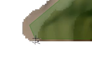
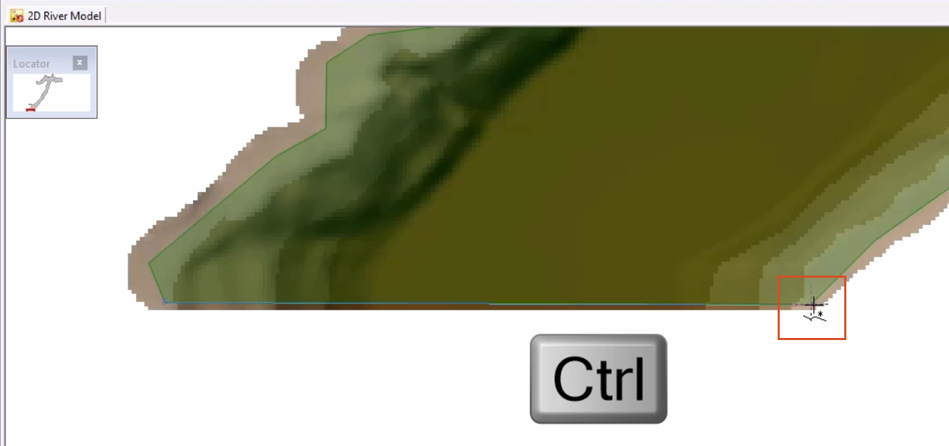
Now digitize a 2D boundary line from left to right, making sure that the line shares the 2D zone vertices of the 2D zone polygon.
05:32
You can use the ALT or CTRL keys to auto-trace and snap to vertices on the 2D zone between the vertices.
05:40
Click the starting point on the 2D zone boundary,
05:44
now hold down the Ctrl key and click on the end point.
05:48
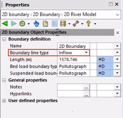
Add a name of “2D Boundary”, ensuring that the name matches that of the inflow object ID within the Inflow event object.
05:58
In the Properties window, set the Boundary line type to Inflow.
06:03
Now that your 2D boundaries are defined, the next step is to generate a 2D mesh.