00:03
In ICM, 2D base linear structures are 2D network objects that allow flexible representation of a range of linear features
00:11
that may be present within the 2D zone surface.
00:15
As they are 2D structures, they may be more appropriate than legacy object types of wall or porous wall
00:21
by using 2D equations to simulate their effect.
00:24
To begin, from the File menu, select Open > Open transportable database.
00:30
Navigate to the folder where you downloaded the files for this tutorial, select the .icmt file, and then click Open.
00:40
If you see a popup about opening the database as read-only, click Yes.
00:45
Right-click the top-level folder and select Copy.
00:49
Right-click the Database and select Paste.
00:53
In the Copying popup, enable Copy ground models, and then click Continue.
00:59
Double-click 2D River Model to open the network on the GeoPlan.
01:03
A 2D mesh has already been created for this model.
01:07
In the Scenarios toolbar, expand the drop-down and select the Base scenario, if needed.
01:13
From the Database, drag the 2D Ground Model onto the GeoPlan.
01:18
It may be helpful to adjust the Ground Model theme to better see the objects and mesh.
01:23
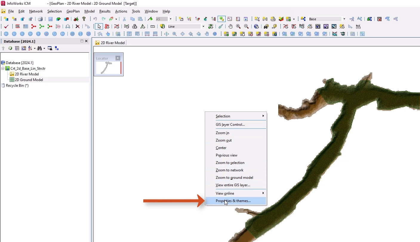
Right-click the GeoPlan and select Properties & Themes.
01:27
On the Layers and Themes tab, for the Ground Model object layer, in the Theme column, click Edit.
01:34
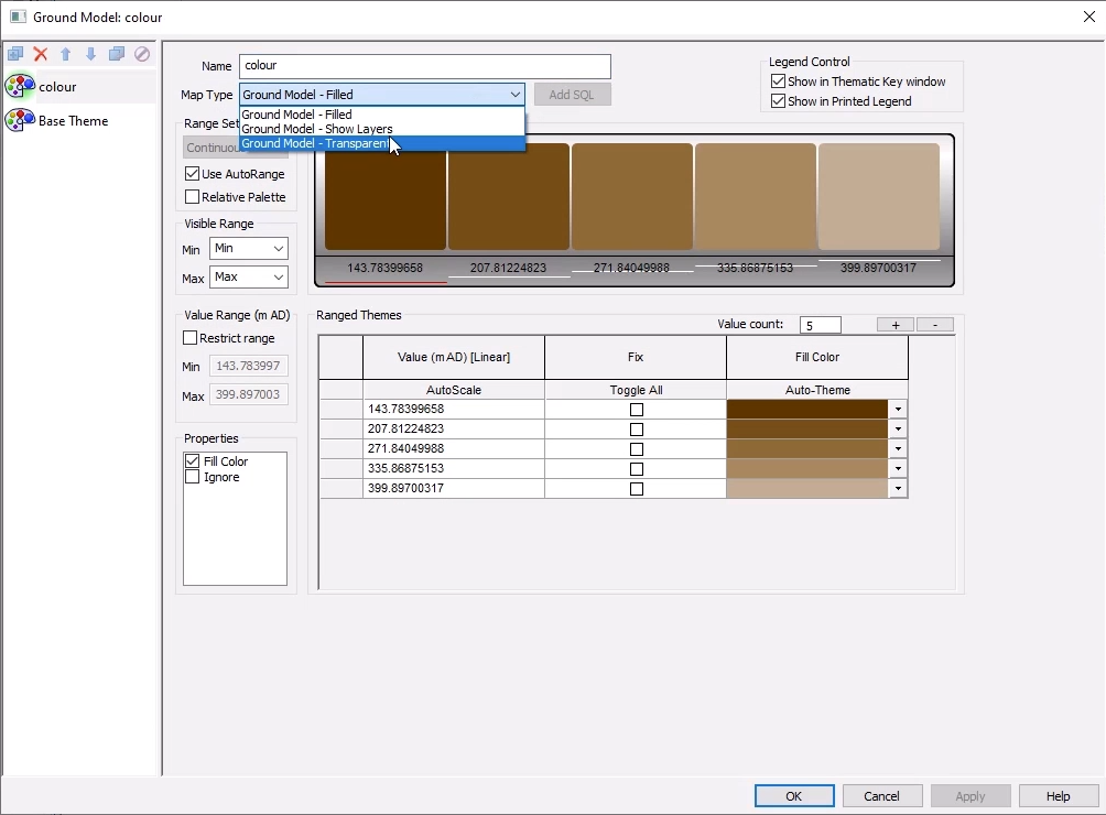
In the Layer Theme Editor, expand the Map Type drop-down and select Ground Model - Transparent.
01:41
Click OK, then OK again to close the GeoPlan Properties and Themes window.
01:46
You can now locate the area to add the 2D base linear structure.
01:51
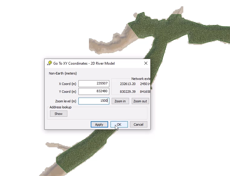
In the GeoPlan Tools toolbar, click Go to xy coordinates.
01:57
In the popup, set the X coordinate to 235507, the Y coordinate to 832480, and the Zoom level to 1500.
02:08
Click OK to close the popup.
02:11
The GeoPlan zooms in to these coordinates.
02:14
Now draw a dam structure across the riverbed in this area.
02:18
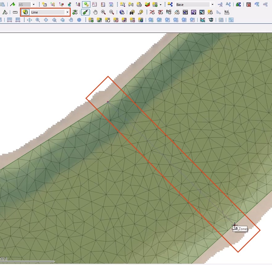
From the GeoPlan Tools toolbar, expand the New Object Type drop-down and select Line.
02:25
Click New Object and draw a line across the width of the 2D zone from left to right.
02:31
Ensure that the line is bigger than the channel bed or flow will be able to pass around it.
02:37
You can use the snap tool to snap to the 2D zone vertices on the edge of the 2D zone domain.
02:43
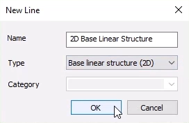
Double-click to finish the line.
02:46
In the New Line popup, add a Name, such as “2D Base Linear Structure”, and set the Type to Base linear structure (2D).
02:57
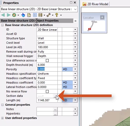
The Properties window for the base linear structure appears, where you can make a few adjustments.
03:02
For this example, you set up a wall with a level of 180 mAD to act as a dam.
03:08
You can also set it up to remove this wall once a threshold is met within the simulation.
03:14
In the Properties window, set the following parameters:
03:18
Structure type: Wall
03:26
Remove wall during simulation: Fully
03:32
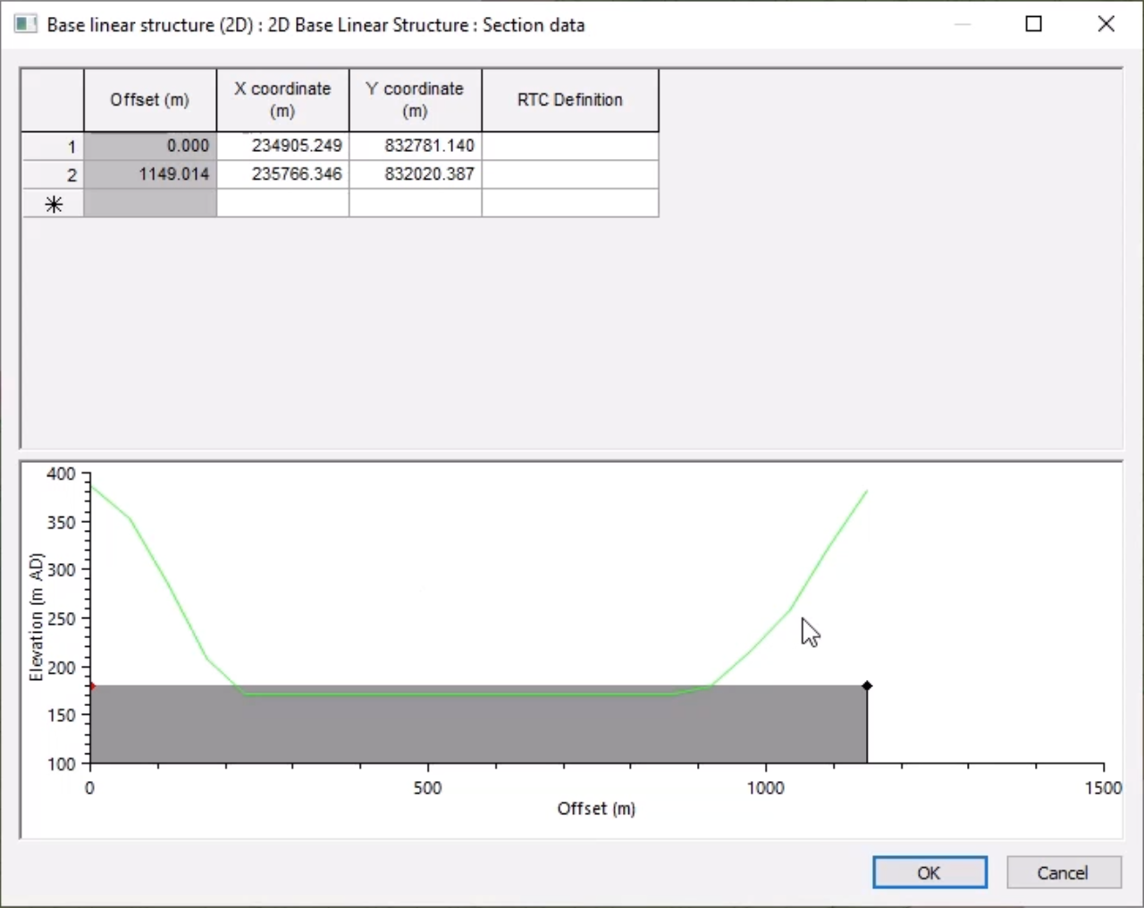
In the Section data field, click the More (…) button to view the profile applied to the structure.
03:38
In the Section data window, the ground model is represented by the green line.
03:43
The 2D element level overrides any levels higher than the structure.
03:48
Click OK to close the Section data window.
03:51
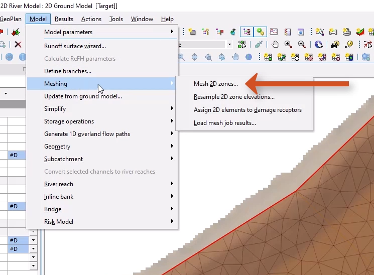
Since you made changes, you need to re-mesh.
03:55
Double-click an area of the 2D zone, and from the Multiple Selection popup, select 2D Zone.
04:03
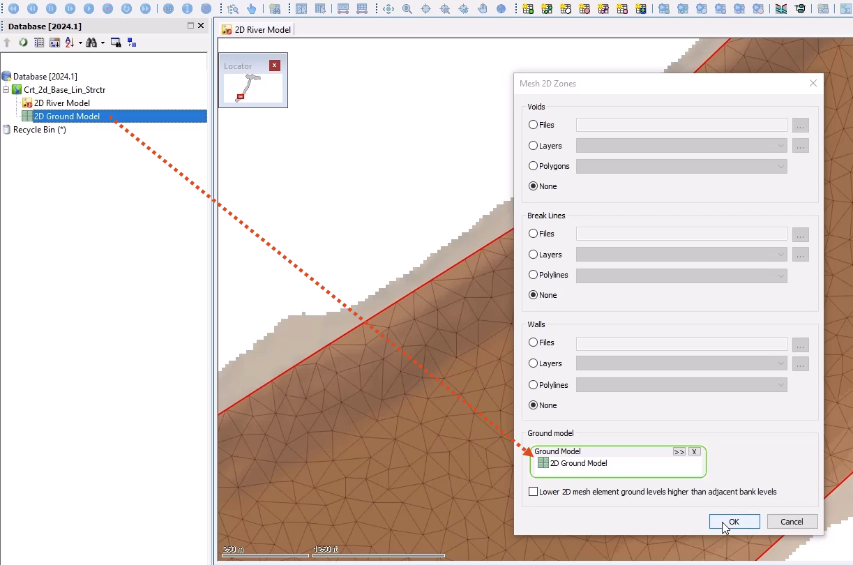
From the Model menu, select Meshing, and then choose Mesh 2D zones.
04:09
In the Mesh 2D Zones dialog, make sure that the Ground model section is populated.
04:15
If not, from the Database, drag the 2D Ground Model and drop it into the Ground Model group box.
04:21
Click OK to mesh the 2D zone.
04:24
In the Schedule Job(s) popup, click OK.
04:28
From the Window menu, select Job control window to display the status of the mesh job and some information on the generation.
04:36
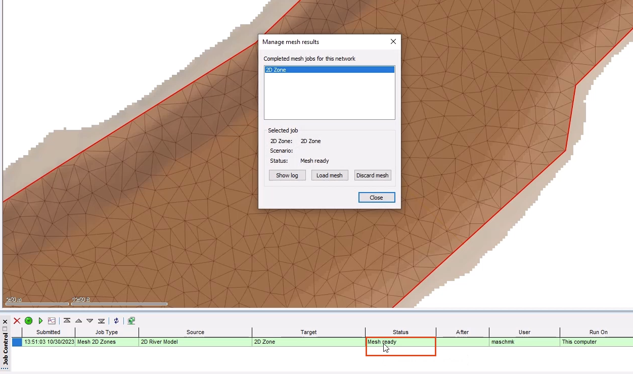
Once the mesh has completed, it can be loaded into the model.
04:40
From the Job control window, click the Mesh ready status to open the Manage mesh results window.
04:46
Click Load mesh, and then Close.
04:50
The 2D base linear structure is incorporated into the mesh.
04:54
Click Validate to make sure there are no errors in your Base network.
05:00
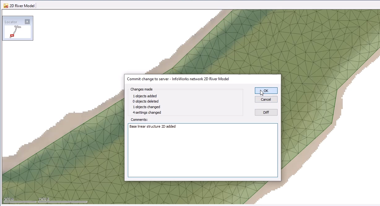
Click Commit changes to database to save your changes.
05:05
Add a comment, such as “Base linear structure 2D added”, and then click OK.