00:11
When modelling the 1D-2D surface interaction,
00:15
node ground levels can vary greatly from ground model data, resulting in inaccurate flows and instability.
00:22
Special attention should be paid to the alignment of node – ground levels and element – ground levels when coupling your model.
00:30
You may need to adjust the node ground level, element ground level, or node location.
00:36
At manholes, the calculation of the water exchange between the node and the mesh element
00:41
depends on which flood type is selected.
00:43
In this example, you look at one potential solution.
00:47
You should always consider what is most appropriate for your specific model and its purpose.
00:53
Open the transportable database Set_2D_Fld_Types.icmt, and then copy it to the database.
01:01
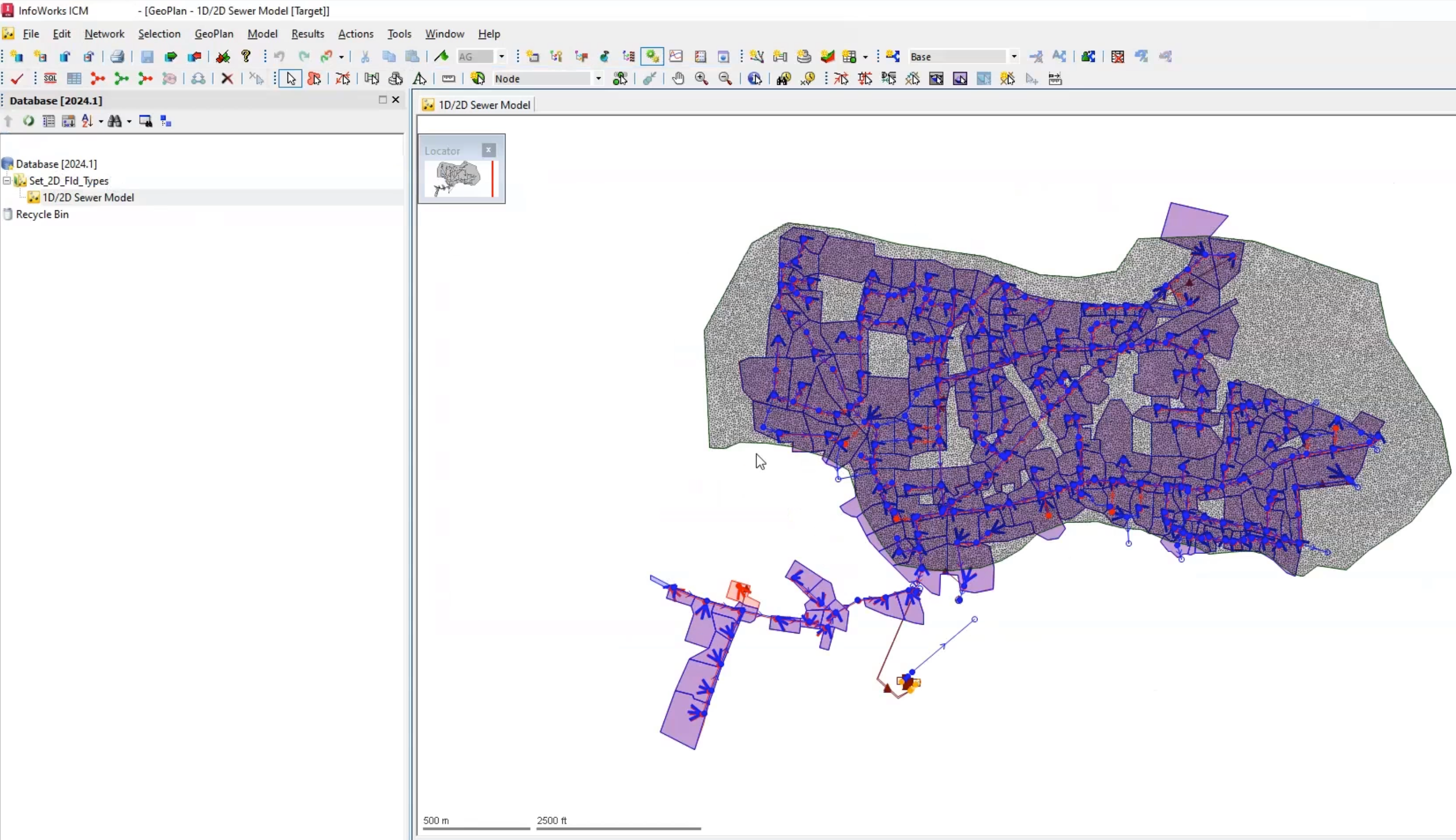
In the Database, double-click 1D/2D Sewer Model to open it on the GeoPlan.
01:07
The 2D zone is already imported and a 2D mesh is generated.
01:11
Now, you can couple the 1D sewer network by setting 2D flood types.
01:16
Select the 2D zone in the GeoPlan.
01:19
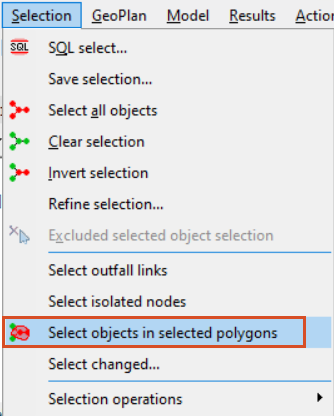
From the Selection menu, click Select objects in selected polygons to select everything within the 2D zone.
01:27
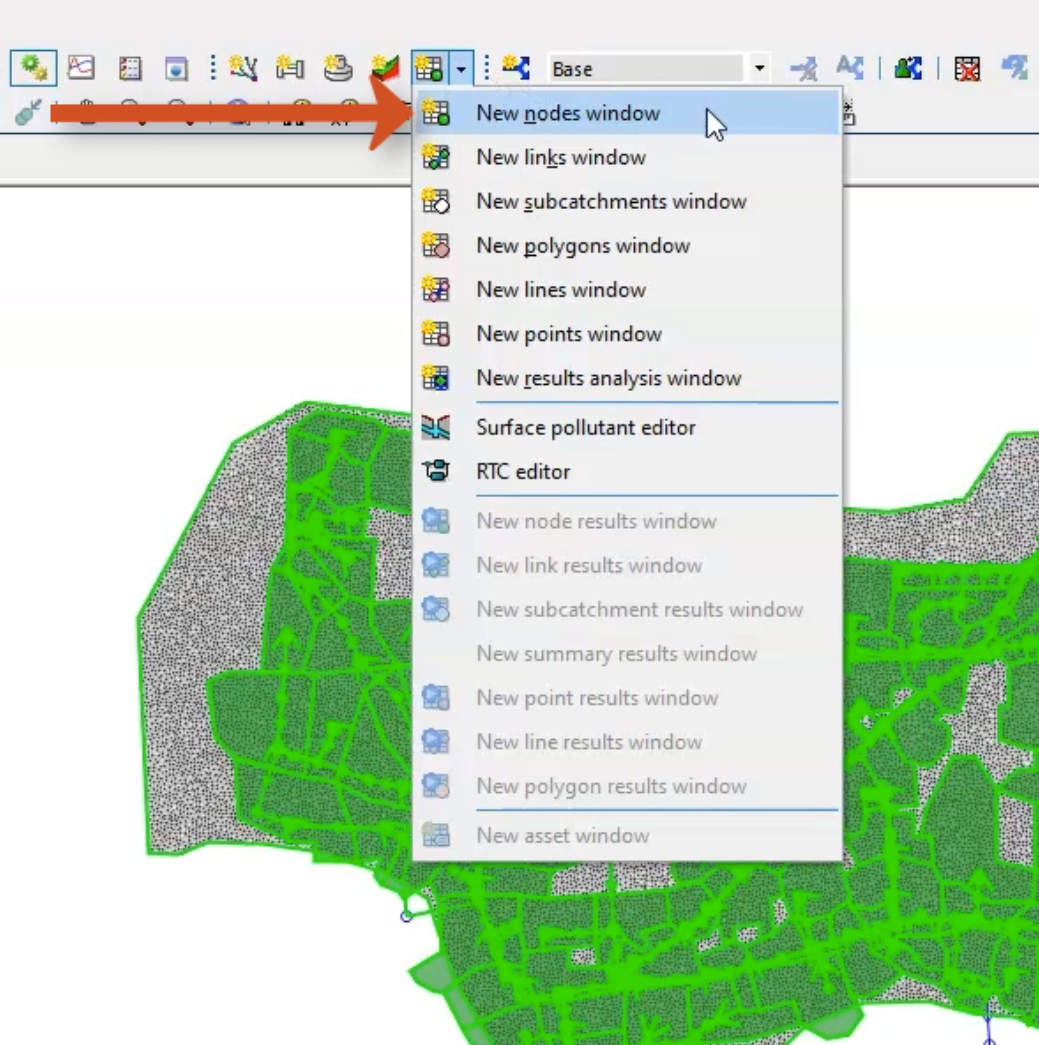
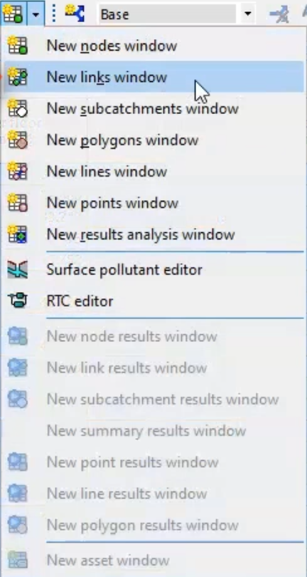
While pressing the CTRL key, in the Windows toolbar, expand the Grid windows drop-down and select New nodes window.
01:36
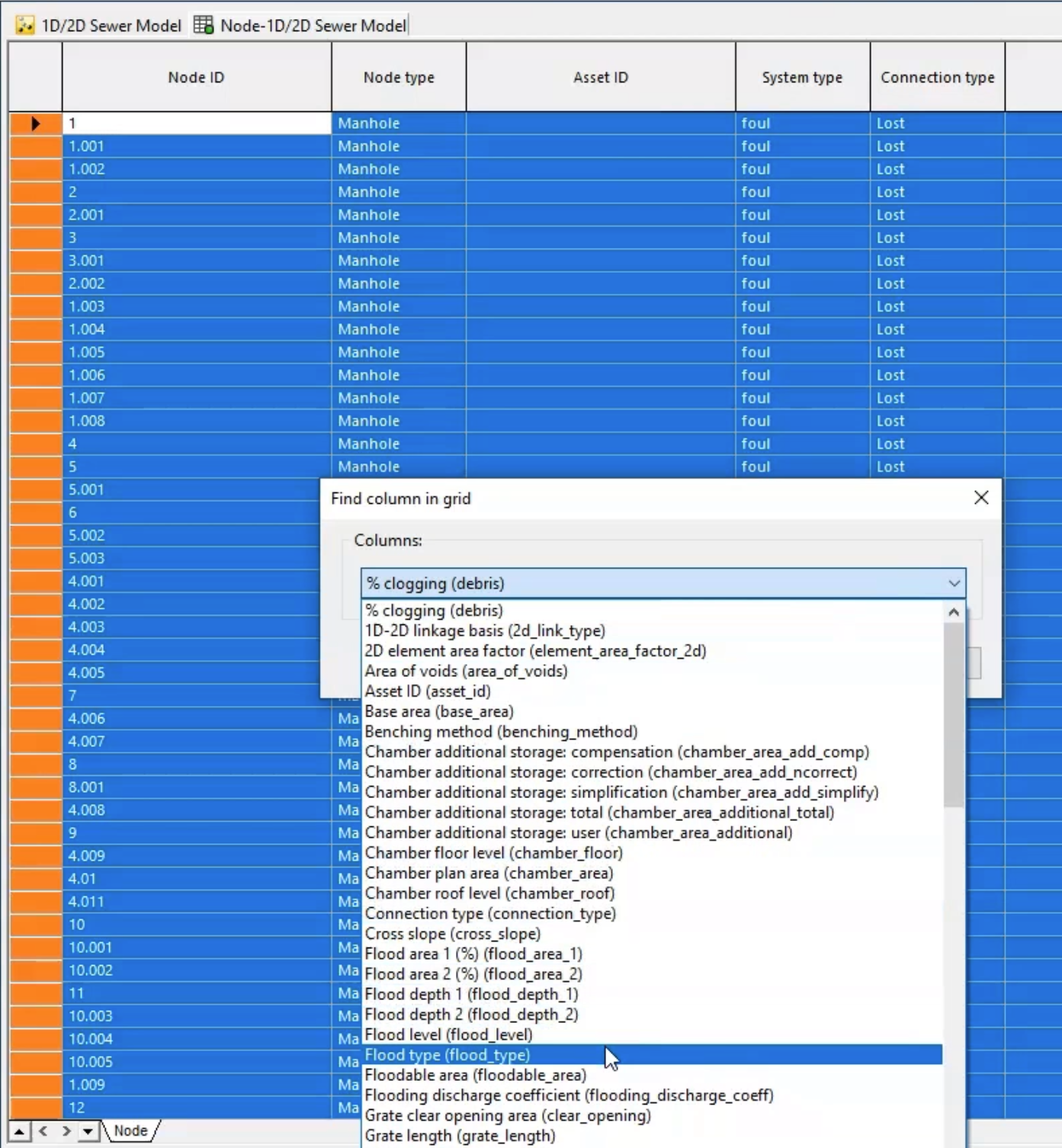
This grid now displays all nodes within the 2D zone.
01:40
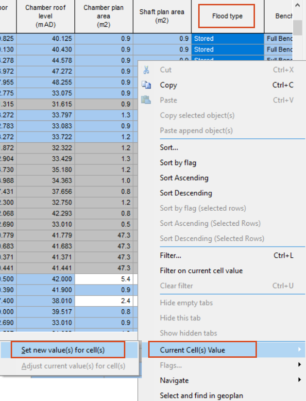
Locate and right-click the Flood type column heading and pick Sort on selected columns descending.
01:47
While pressing the SHIFT key, select all fields with a value of Stored.
01:53
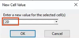
Right-click the selection and select Current cell(s) value > Set new value(s) for cell(s).
02:00
In the New Cell Value popup, select 2D, and then OK.
02:05
For a 2D flood type, the exchange of water between the 2D manhole and the mesh is calculated using the weir equation,
02:12
assuming a weir crest level at the node ground level and crest length equal to the node shaft circumference.
02:19
This will be appropriate if you want a relatively free exchange of flow both in and out of the sewer system.
02:25
For instance, where you have a surface water system,
02:28
but the individual gullies have not been modelled.
02:31
Scroll to the Flooding discharge coefficient column.
02:34
A flooding discharge coefficient equivalent to the weir discharge coefficient is specified for the node.
02:40
The rows should have a default value of 0.5.
02:44
If not, you can populate the values.
02:47
Next, you are going to assign the Gully 2D flood type to the nodes which are currently set as Lost.
02:53
However, you first need to define the head-discharge relationship that these nodes will follow.
02:58
From the Grid windows drop-down, select New links window.
03:03
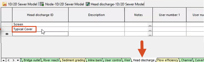
At the bottom of the grid window, scroll to the Head discharge tab.
03:07
This is currently populated with a screen head discharge table.
03:12
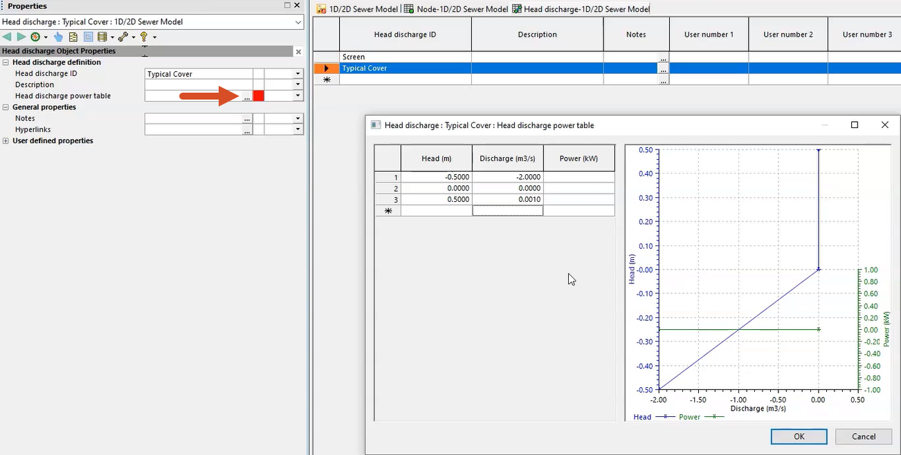
In the Head discharge ID column, select the cell below Screen and enter an ID of “Typical Cover”.
03:18
This generates a new table entry.
03:21
In the far-left cell of this row, double-click to open the table Properties window.
03:27
In the Head discharge power table field, click More (…).
03:31
In the Head discharge window, enter these values into the table:
03:36
Row 1: Head -0.5 and Discharge -2
03:42
Row 2: Head 0 and Discharge 0
03:47
Row 3: Head 0.5 and Discharge .001
03:53
Negative values in this table represent flooding onto the 2D zone, and positive values represent flow entering the sewer system.
04:01
This table has been set up to allow minimal flow into the node from the surface,
04:06
while allowing a relatively free discharge of flow (flooding) onto it.
04:10
This would be most appropriate for foul or sanitary sewers, or where the gully connections are represented in detail.
04:20
Return to the nodes grid window.
04:23
In the Flood type column, use the SHIFT key to select all fields with a value of Lost.
04:29
Right-click the selections and click Current cell(s) value > Set new value(s) for cell(s).
04:37
In the New Cell Value popup, select Gully 2D, and then click OK.
04:43
For a gully 2D flood type,
04:46
the exchange of water between the 2D manhole and the mesh is calculated using a head discharge relationship.
04:53
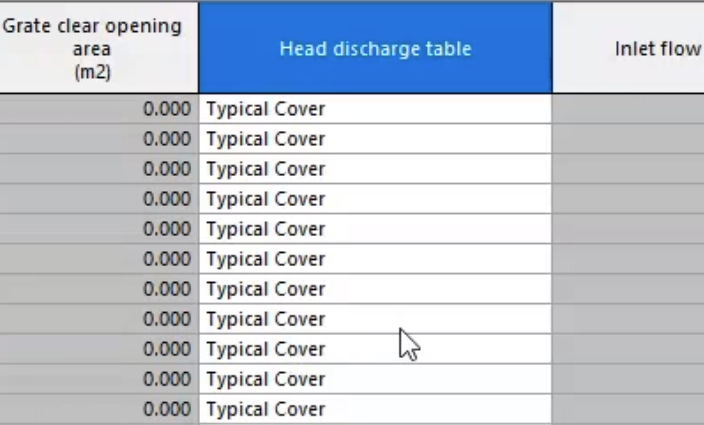
Scroll to the Head discharge table column, which should be populated with the Typical Cover table that you just created.
05:02
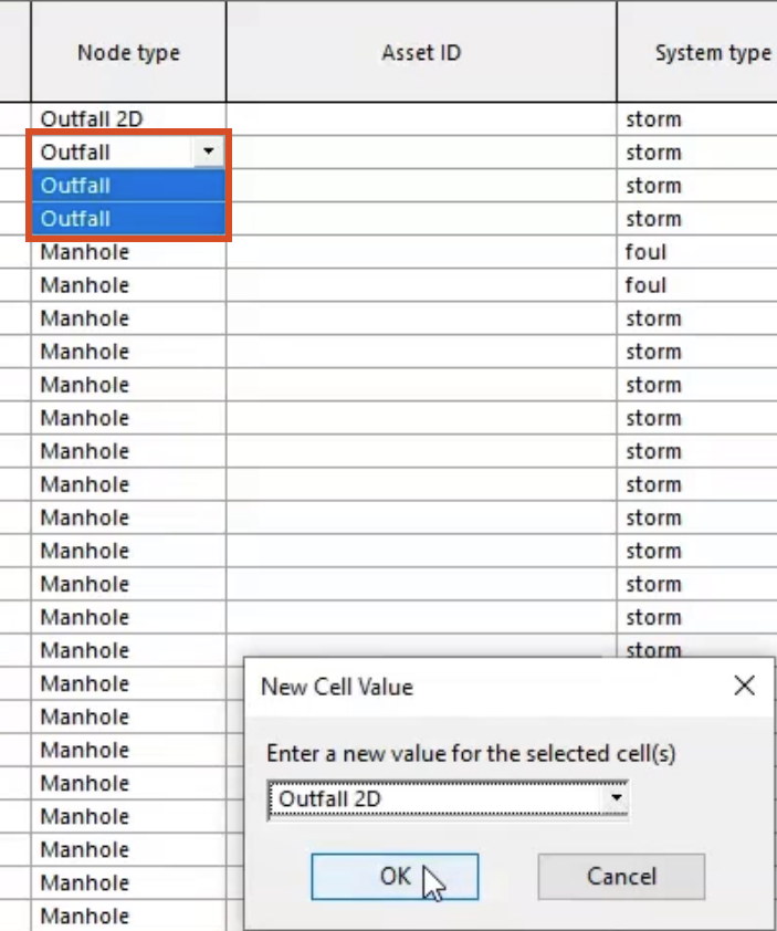
The last update to make is to the outfall nodes.
05:05
In the nodes grid window, right-click the Node type column heading
05:09
and select Sort on selected column(s) descending so that the outfall nodes appear at the top of the list.
05:16
Select the Outfall values.
05:19
Right-click the selection and click Current cell(s) value > Set new value(s) for cell(s).
05:25
In the New Cell Value popup, select Outfall 2D, and then click OK.
05:31
The 2D outfall is used to allow the exchange of water between an outfall and a 2D element.
05:37
These outfalls will now interact with the 2D mesh rather than the flow being lost from the system.
05:44
Click Validate to make sure there are no errors in your network, then click OK.
05:49
Click Commit changes to database to save your changes.
05:53
Add a comment, such as "Added connections for 1D nodes to 2D".