00:03
RTC can be defined for one or more regulators—control elements that can physically regulate flow, depth, or velocity values in the network.
00:14
This example uses RTC to store flow in an upstream tank to reduce the spill from the downstream storm tank,
00:22
and to control the release of flow from the tank.
00:26
To complete this exercise, open the transportable database .icmt file for this tutorial.
00:33
Then, in the Model Group, open the 1D Simulation Model by double-clicking the network or by dragging it onto the GeoPlan.
00:42
To begin, create a new scenario to which you can apply the RTC.
00:48
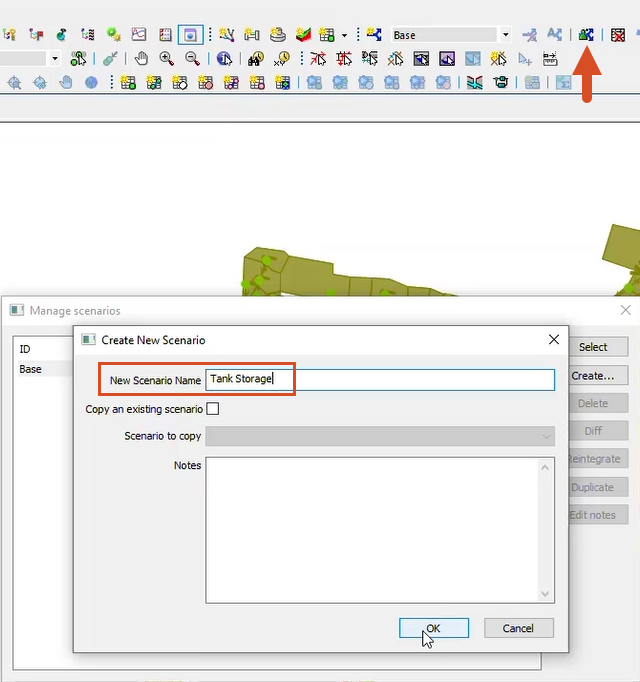
Click Create scenario.
00:50
In the Create New Scenario dialog, enter the name “Tank Storage”, and then click OK.
00:57
Next, use the Find in GeoPlan tool to perform a Quick Find for Storm_Tank1.1.
01:05
Once the tank is located, close the Quick Find dialog box.
01:10
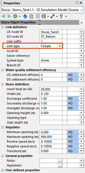
Double-click the upstream node to open its properties.
01:14
You can only apply RTC to certain link types, or more specifically, to links with variable properties.
01:22
In this example, the Link type is currently set to Sluice.
01:27
Use the drop-down to change it to VSGate, which is a variable vertical sluice.
01:34
Once you make the change, regulator properties are added to the Properties dialog.
01:39
Make sure that you are still in the Tank Storage scenario.
01:43
Then, click the Grid windows drop-down and select RTC editor.
01:49
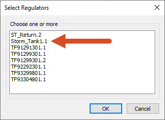
In the RTC Window Editor, right-click Global and select Insert regulator.
01:56
The Select regulator popup appears, displaying all the regulator links in the model that can be controlled via RTC.
02:05
Select Storm_Tank1.1, and then click OK.
02:10
The regulator is added to the RTC tree structure, and you can now define the rules for it to follow.
02:17
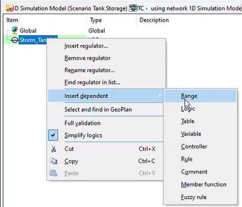
In this example, you want to keep the sluice gate shut, unless the level within the inlet channel is less than 41.00m AD.
02:28
To do this, right-click Storm_Tank1.1, select Insert dependent, and then select Range.
02:37
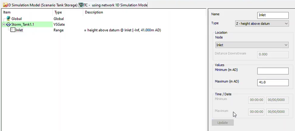
Expand the Storm_Tank1.1 entry and select NewRange to display its settings in the right-hand pane.
02:45
Set the following: Name: Inlet Type: Z - height above datum Location: Inlet Maximum (m AD): 41.000
03:02
Click Update to save the information.
03:05
You can now define the rules.
03:08
The variable for the VSGate is the opening height.
03:11
Right-click Storm_Tank1.1, select Insert dependent, and then select Rule.
03:19
Set the Condition to _Default_, and the Type to POS.
03:26
The Setpoint Type should be Fixed at 0.000.
03:32
Click Update to save the information.
03:35
Next, define a second rule for when the sluice should open.
03:39
Again, right-click Storm_Tank1.1, select Insert dependent, and then select Rule.
03:48
Set the Condition to Inlet, which looks at the Range that you set earlier.
03:53
Set the Type to POS and the Setpoint Type to Fixed at 0.150.
04:02
Select the regulator Storm_Tank1.1, and in the Description box, notice the description of the rules that you just added.
04:12
This is useful to read and determine whether your RTC is logical.
04:17
Now, define the rules for your upstream storage tank.
04:21
You want the tank to contain flow when the downstream pumping station is on,
04:26
and hold back the water until the online tank has drained.
04:30
Leave the RTC Window Editor open and switch back to the model on the GeoPlan.
04:37
Click Find in GeoPlan and perform a Quick Find for link TF92290601.1.
04:47
Once the link is located, close the Quick Find dialog.
04:51
To change link TF92290601.1 from a conduit to a regulator link,
04:60
you need to delete it and then recreate the link.
05:03
Confirm that only the link is selected, and then click Delete selection.
05:10
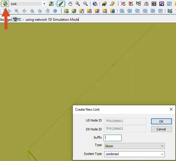
Expand the New Object drop-down and select Link, then click the New object tool and draw a link from TF92290601 to TF91299602.
05:26
In the Create New Link dialog, set the Type to Sluice, and then click OK.
05:32
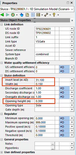
In the Properties dialog for the new sluice, set the Link type to VSGate.
05:38
Under Sluice definition, set the Invert Level (m AD) to 31.100, the Width (m) to 0.150, and the Opening height (m) to 0.300.
05:56
Switch back to the RTC Window Editor.
05:59
Right-click Global and select Insert regulator.
06:04
In the Select Regulators dialog, select TF92290601.1, and then click OK.
06:15
You can now set up the rules for this regulator.
06:18
Right-click TF92290601.1, select Insert dependent, and then select Rule.
06:29
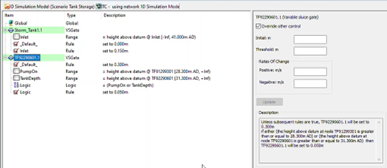
Expand the TF92290601.1 entry and select the NewRange item to display its settings.
06:40
Set the Condition to _Default_, the Type to POS, and the Setpoint Type to Fixed at 0.3 m.
06:54
Again, right-click TF92290601.1, select Insert dependent, and then select Range.
07:05
Set the Name to “PumpOn”,
07:08
the Type to Z – height above datum,
07:12
the Node to TF91299301,
07:18
and the Values Minimum (m AD) to 28.300.
07:26
Then, set up a second Range,
07:30
and this time, set the Name to “Tank Depth”,
07:34
the Type to Z – height above datum,
07:37
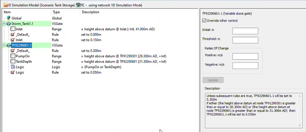
the Node to TF92290601, and the Values Minimum (m AD) to 31.300.
07:51
You want the sluice to remain at a 50mm opening height during both of the range conditions.
07:57
You can do this using a logic table.
07:60
Right-click TF92290601.1, select Insert dependent, and then select Logic.
08:10
Set the Name to “Logic” and the Operator to OR.
08:15
In the Dependent Conditions drop-downs, select the two ranges that you defined, PumpOn and TankDepth.
08:25
Finally, you need to create a new rule that looks at the logic you just created
08:30
as its condition and that sets the opening height of the sluice.
08:34
Right-click TF92290601.1, select Insert dependent, and then select Rule.
08:45
Set the Condition to Logic, the Type to POS, and the Setpoint Type to Fixed at 0.050 m.
08:57
Your RTC is now finalized.
09:00
Once again, you can click regulator TF92290601.1
09:08
and read through the Description to make sure everything looks logical.
09:12
Then, close the RTC Window Editor.
09:15
To use this RTC in a simulation, first, you need to validate and commit your latest changes.
09:25
In the Network Validation popup, select the Tank Storage Scenario, and then click OK.
09:31
Ensure that there are no errors in the Output Window, and then click Commit changes.
09:38
In the popup, add the comment “RTC added at two sluices”, and then click OK.
09:46
You are now ready to test the impact that the addition of the sluice and RTC have on the model and the spills from the storm tank.