00:03
The inline bank is a control object that can be used to act as a connection between 1D and 2D parts of the network.
00:12
Once bank lines are created and inline bank links are drawn in the direction of flow to intersect these bank lines,
00:20
you can build the 1D-2D connection.
00:23
Open the transportable database .icmt file for this tutorial.
00:29
In the transportable database window, right-click the top-level folder, and select Copy.
00:36
In the popup, click Continue.
00:40
Right-click the Database and select Paste (with children).
00:45
In the Copying pop-up, enable Copy ground models.
00:51
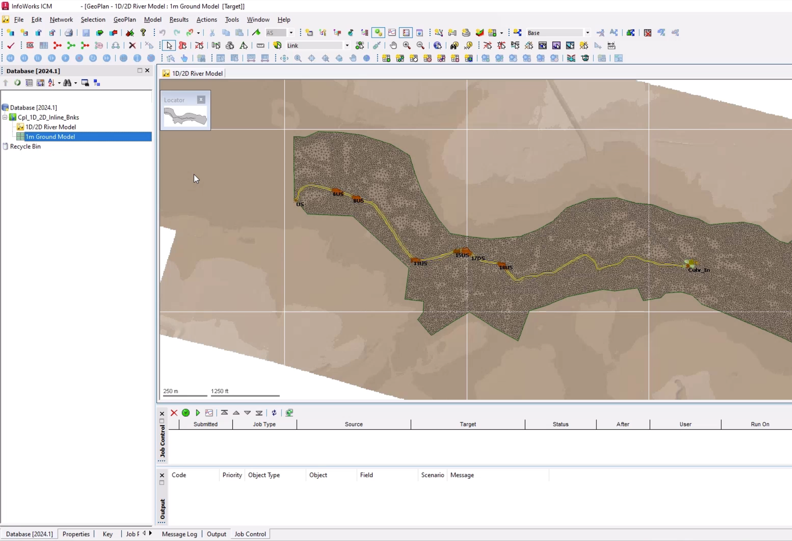
Then open 1D/2D River Model and 1m Ground Model on the GeoPlan.
00:59
Bank lines and inline banks are already created.
01:04
In this example, you build their connection to the 2D zone.
01:08
In the GeoPlan Tools toolbar, click Find in GeoPlan and perform a Quick Find for Culv_Out.
01:17
Once the node is located, Close the Quick Find window.
01:21
Building the connection is a very simple process.
01:25
You can either manually set the 2D Zone ID field or use the inbuilt tool.
01:32
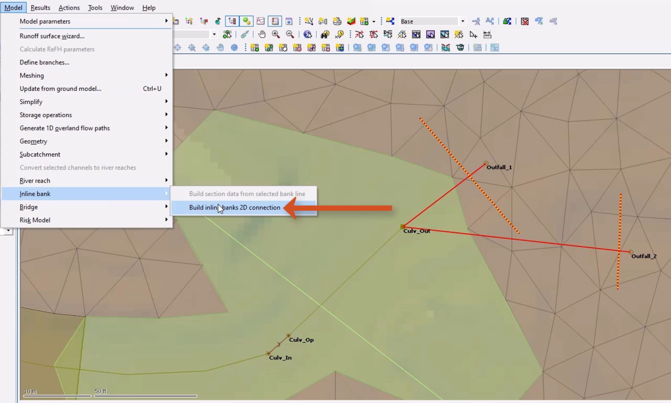
To use the tool, make sure that both inline banks are selected.
01:37
From the Model menu, select Inline bank > Build inline banks 2D connection.
01:45
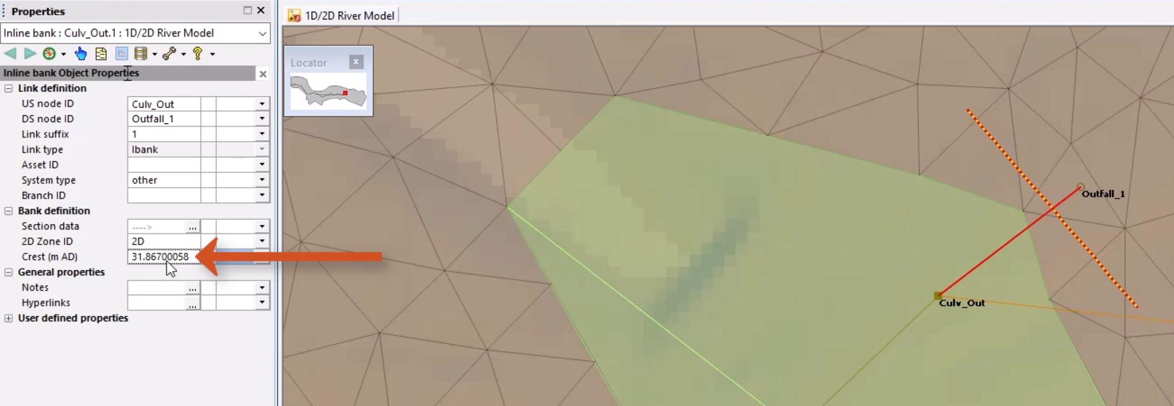
Finally, you need to set the outfall levels for the inline bank.
01:50
Double-click the first inline bank to open the Properties window.
01:54
Copy the Inline bank – Crest (m AD) value.
01:59
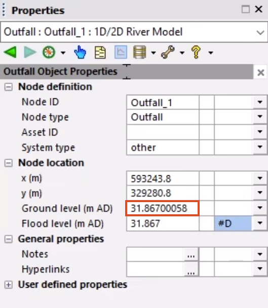
Double-click the associated outfall node to open the Properties window.
02:05
Paste the value in the Outfall – ground level (m AD) field.
02:10
Repeat for the second inline bank and outfall node.
02:15
This could be automated via SQL.
02:18
The object data should now be fully populated for both inline banks without any errors.
02:25
Since you have made changes, you need to regenerate the mesh.
02:30
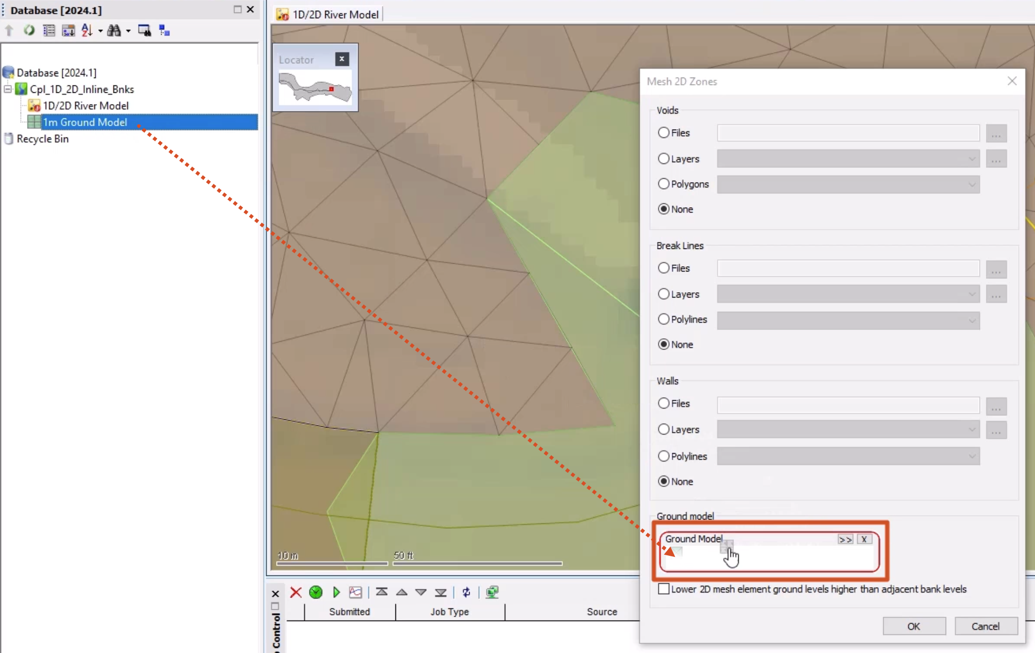
With the 2D zone selected on the GeoPlan, select Model > Meshing > Mesh 2D zones.
02:38
From the Database, drag the 1m Ground Model into the Mesh 2D Zones dialog and drop it into the Ground Model group box,
02:52
In the Schedule Job(s) dialog, click OK.
02:57
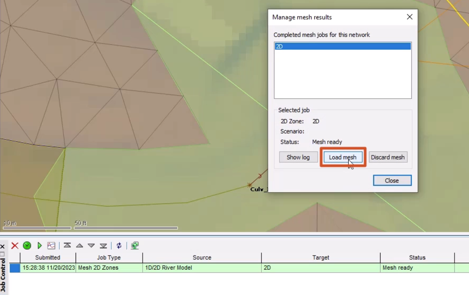
Once the mesh has completed, from the Job control window,
03:01
click the Mesh ready status to open the Manage mesh results window.
03:07
Click Load mesh, and then Close.
03:11
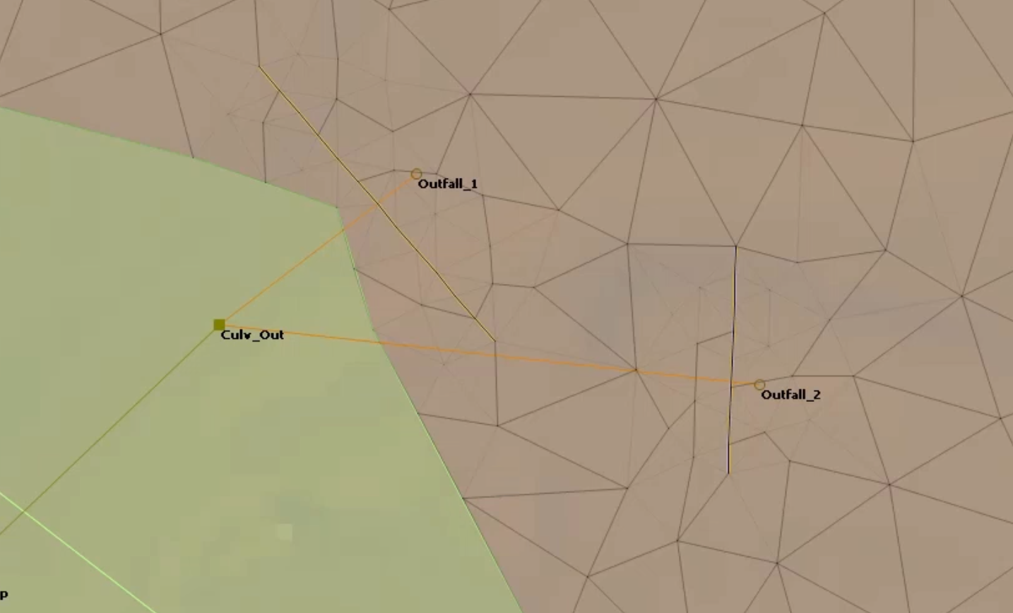
You can see that the bank lines are correctly connected to the 2D zone,
03:16
highlighted by the blue element bank edges.
03:20
To help visualize the effect that vertices have on the mesh triangle generation and element aggregation,
03:28
on the GeoPlan, right-click the model and select Properties & themes.
03:34
On the Elements tab, in the 2D elements section for Internal edges,
03:40
click More (…) to change the color to red.
03:46
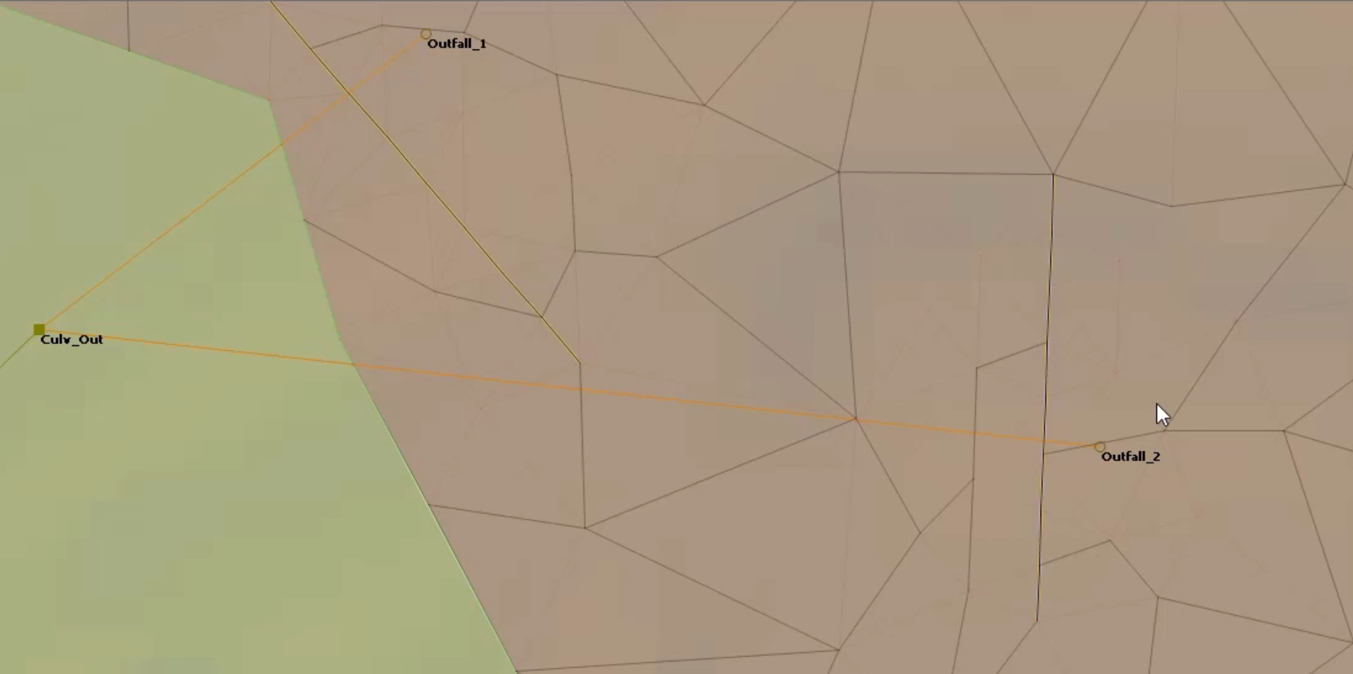
On the GeoPlan, zoom in to see that many internal edges (triangles) have been generated around the inline banks,
03:55
as they have vertices every 2m.
03:59
This demonstrates how adding features can increase mesh generation time.
04:05
This can also lead to the generation of small elements or elements containing many triangles,
04:11
especially with the classic methodology.
04:15
Click Validate to make sure there are no errors in your network, and then click OK.
04:21
Click Commit changes to database to save your changes.
04:26
Add a comment, such as "Added inline banks". Click OK.