00:03
Bridges are critical structures in river modelling and can significantly influence hydraulics.
00:10
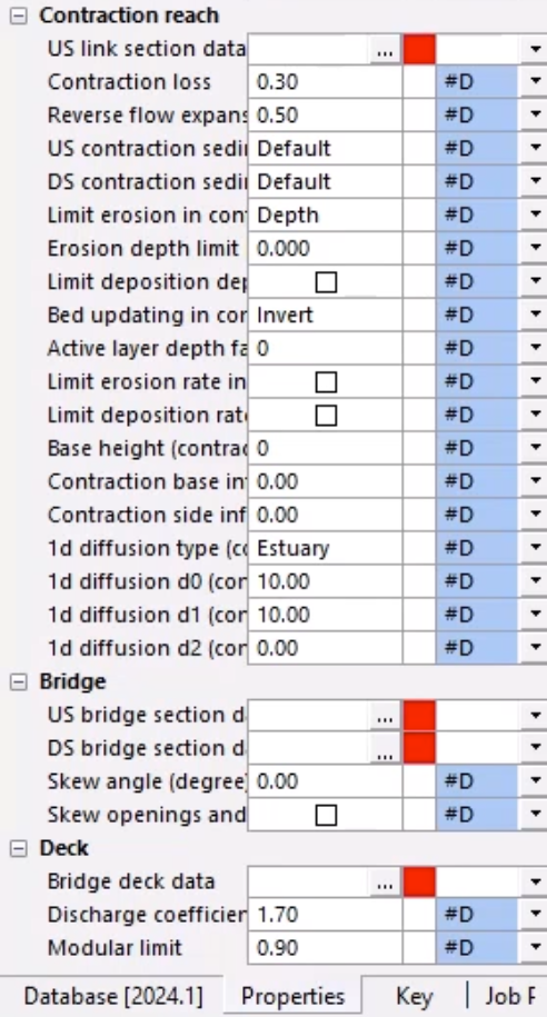
Bridges in ICM have 5 sections:
00:15
Contraction reach: Cross section upstream of the bridge.
00:19
US bridge section: Cross section directly upstream side of the bridge.
00:25
DS bridge section: Cross section directly downstream side of the bridge.
00:31
Expansion reach: Cross section downstream of the bridge.
00:36
Deck: Cross section of the bridge deck.
00:40
Cross section lines are required for each of these sections.
00:44
For this example, cross-section survey data has already been imported.
00:49
To complete this exercise, open the transportable database .icmt file for this tutorial
00:56
or continue from the previous lesson.
00:60
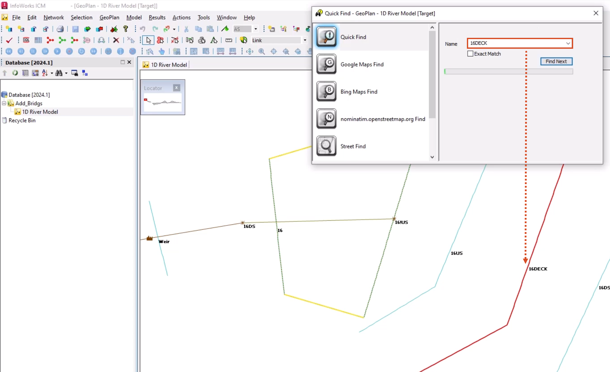
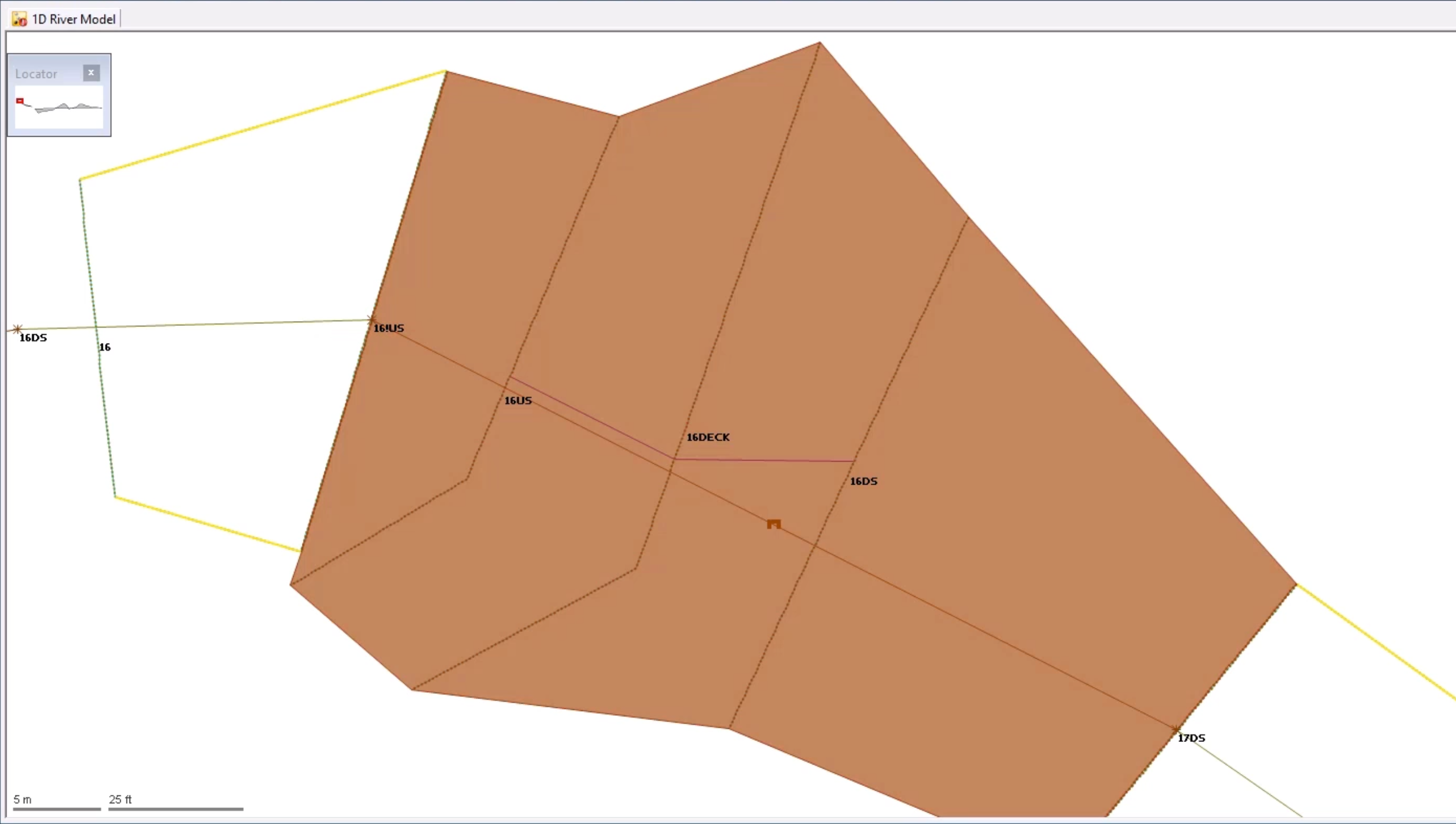
In the Explorer, under the Database, double-click the 1D River Model to open it on the GeoPlan.
01:08
Click Find in GeoPlan and perform a Quick Find for 16DECK.
01:14
Once the deck is located, close the Quick Find window.
01:18
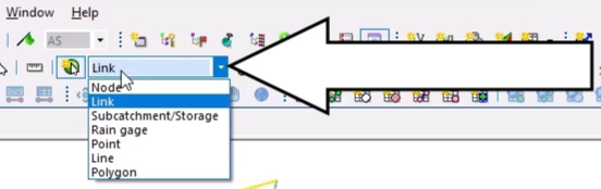
From the GeoPlan Tools toolbar, expand the New Object Type combo box and select Link.
01:26
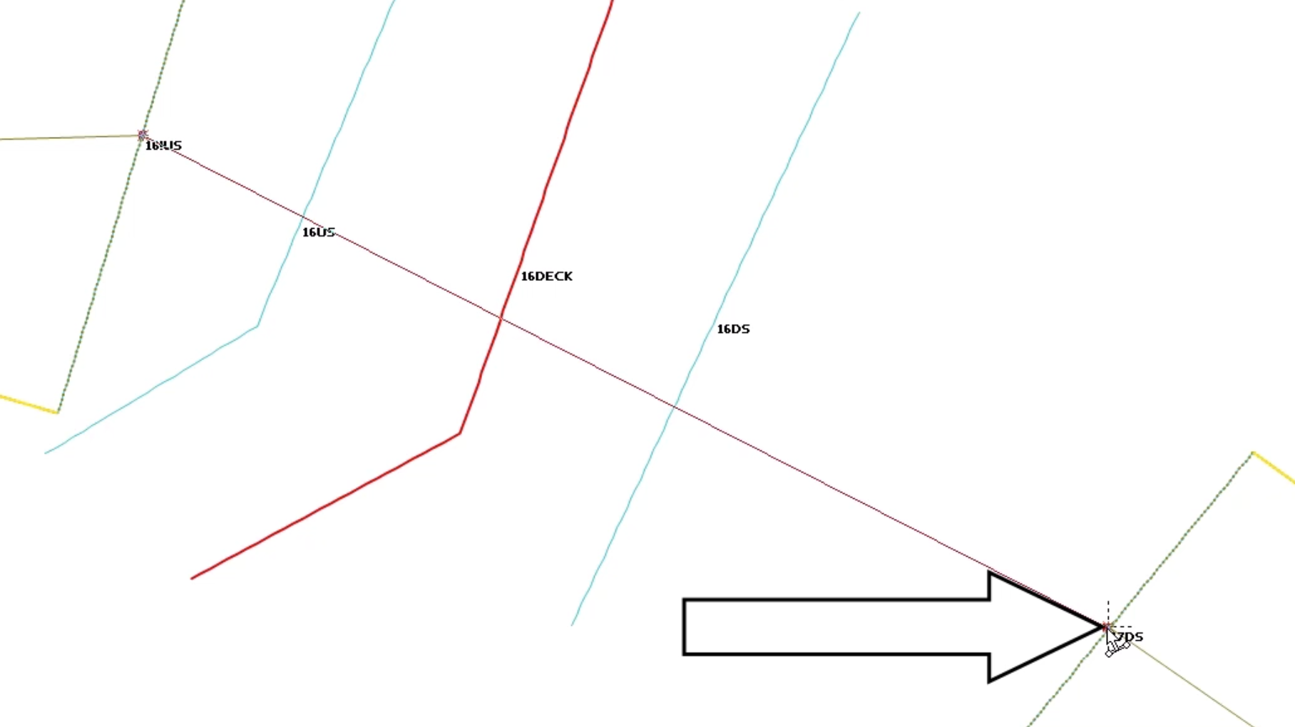
Draw a new link between the two break nodes, from upstream node 16!US to downstream node 17DS.
01:38
In the Create New Link popup, set the Type to Bridge, and then click OK.
01:44
The new bridge link will appear in the properties window with inline validation errors against all of the empty section data.
01:53
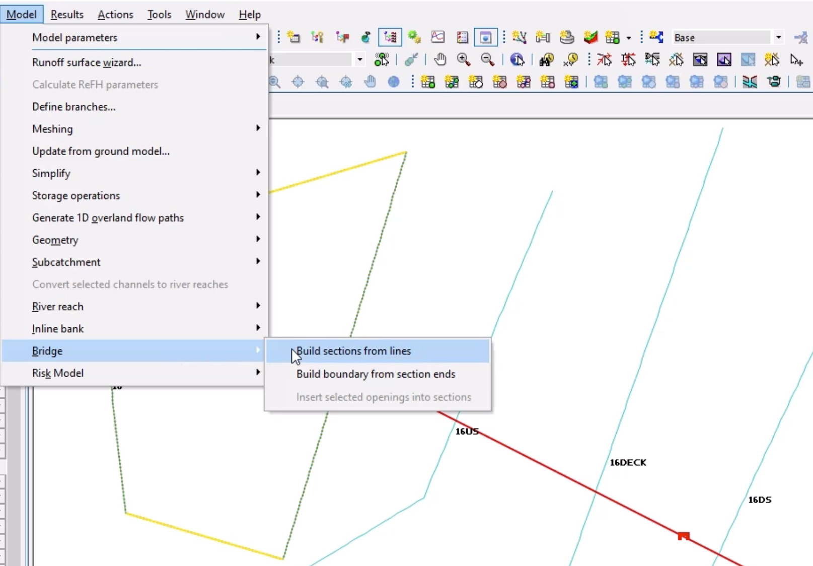
Using the Select tool, on the GeoPlan, select the new Bridge link you just added.
01:60
From the Model menu, select Bridge, and then select Build sections from lines.
02:07
The Bridge Operation report displays information on how it has associated the cross section data.
02:15
Open the US link section data to view the imported data.
02:20
The inline validation messages remain due to the missing roughness values.
02:26
The next step is to add bridge openings, so that water can flow through.
02:31
From the GeoPlan Tools toolbar, expand the New Object Type combo box, and this time, select Line.
02:40
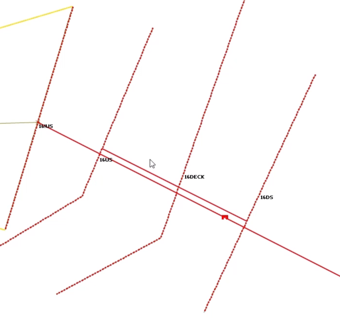
Click Create New Object and draw a bridge opening from left to right (downstream) parallel to,
02:47
or on top of, the bridge link—as close as you can to the center line.
02:53
This line must extend slightly beyond both the upstream 16US and downstream 16DS cross sections.
03:02
To finish digitizing the line, double click the final point.
03:08
In the New Line popup, add the name “Opening_1” and set the Type to Bridge opening.
03:18
Once the opening has been drawn, its parameters need to be defined.
03:23
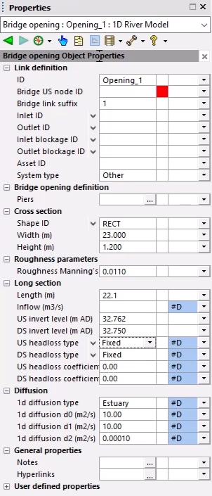
In the Properties window for the new Bridge opening, set the following parameters:
03:40
Roughness Manning's n: 0.0110.
03:49
US invert level: 32.762.
03:54
DS invert level: 32.750.
03:59
The upstream and downstream invert levels are the same as those of the upstream and downstream bridge face cross sections.
04:08
There is still one validation error in the Bridge US node ID field.
04:14
To resolve this error, you can insert the opening into the bridge section.
04:20
Firstly, enable the Skew openings and piers option on the bridge link.
04:26
Using the Select tool, select the bridge and the bridge opening.
04:31
From the Model menu, select Bridge, and then select Insert selected openings into sections.
04:39
Notice that once this is complete, the opening is trimmed to the bridge face cross sections.
04:46
The bridge opening can now be viewed by going to the Bridge Properties window.
04:51
There are roughness validation errors for the US bridge section data and DS bridge section data fields,
04:58
but you may also see another error, such as “d/s bed is at or above soffit of opening”.
05:06
In this example the error is on the DS bridge section data.
05:11
Click the ellipsis (…) button to open the Bridge section data window.
05:16
In the graph, make sure the bridge opening is within the channel.
05:20
If the opening is not shown, no flow will be transferred through the opening.
05:25
You can alter the opening position to fix the error.
05:30
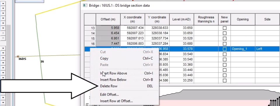
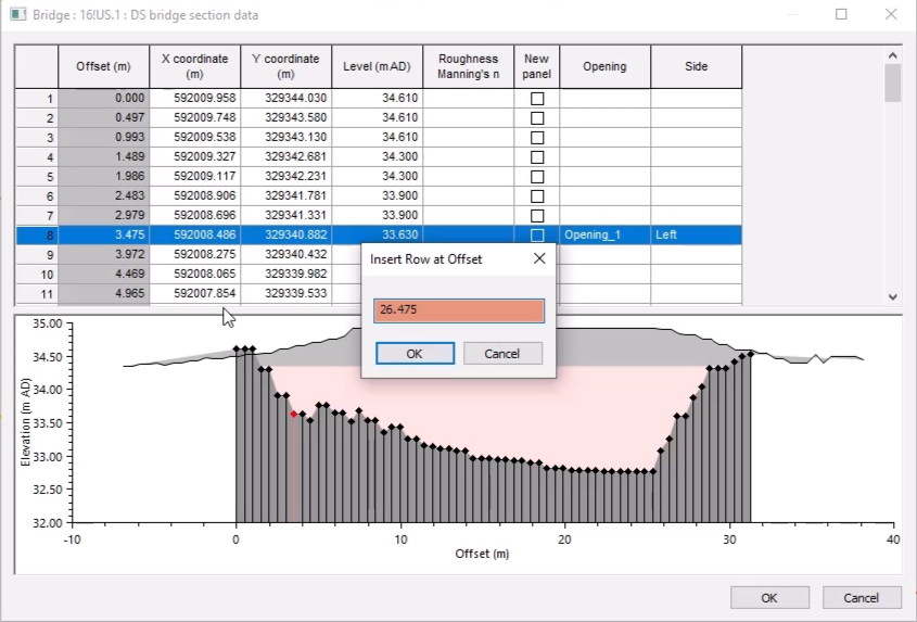
Remove the rows with entries in the opening and side columns.
05:35
In the graph, locate the true left side of the opening.
05:39
In the table, for the corresponding row, Here the row is at offset 3.475m.
05:47
Expand the Opening column drop-down and select Opening_1.
05:54
In the Side column, select Left.
05:57
Right-click the row ID and select Insert Row at Offset.
06:03
Since you know that the bridge opening is 23 meters wide, add 23 to the amount in the popup field.
06:11
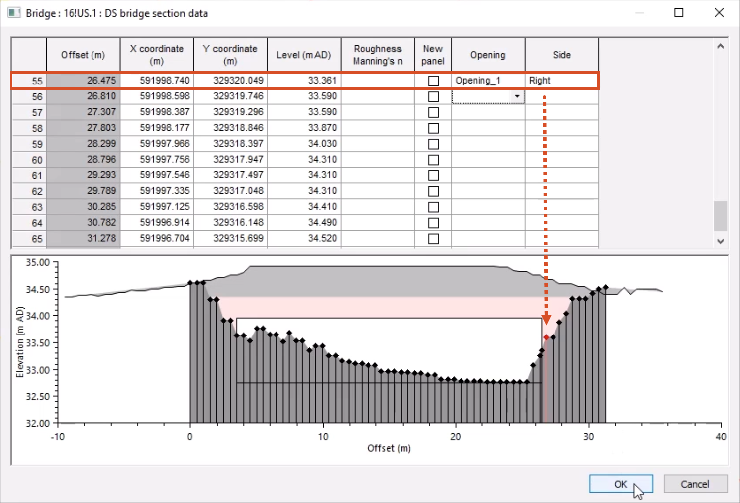
In this case, change 3.475 to 26.475, and then click OK.
06:21
Scroll down to the row with this Offset value and for the Opening column, select Opening_1.
06:29
In the Side column, select Right.
06:32
The opening will now appear in its new position on the graph.
06:37
Once you are happy with the location of the bridge opening within the cross sections, you can build a boundary for the bridge.
06:44
From the Model menu, select Bridge, and then select Build boundary from section ends.
06:51
This boundary signifies that the bridge is not meshed as part of any 2D meshing process
06:58
and is the region which will be used for the flood theme.